

Rules
The Rules Module allows you to:
- Create rules for device points using node-based editors.
- Save an unlimited number of rules individually for later editing.
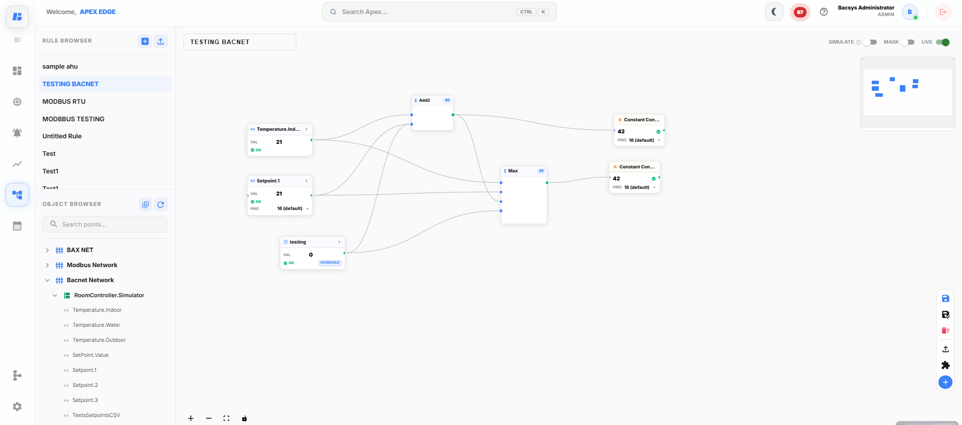
To access the Device Module:
- Click on the Rules icon on the main menu.
- Click on the Menu icon on the top left to view the browser menu.
- Alternatively, click on (>) to Expand or (<) Collapse the browser menu.
- The browser menu lists all created rules under Rules tab and all available points of device in the Object browser tab.
Rules
Creating a New Rule
-
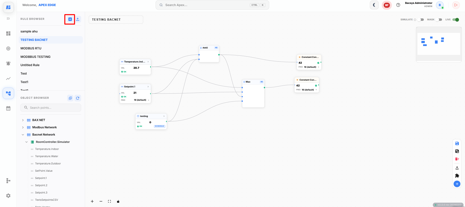
Click on the Create New Rule button located in the Rules browser pane.
-
Enter the name of the rule in the Name field at the top left corner of the canvas.
-
Drag and drop the desired device points from the object browser pane to the canvas.
-
Drag and drop the required blocks from the blocks pane at the right side of page to the canvas.
-
Make the necessary connections between the blocks to complete the rule.
-
Click the Save icon to save the rule.
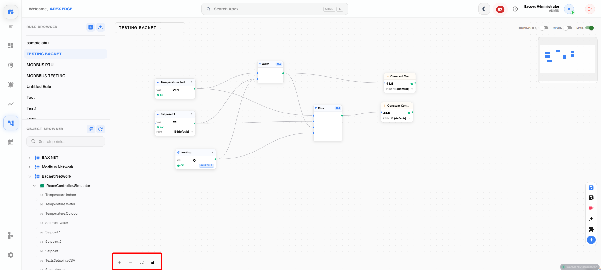
Canvas Options
| Option | Description |
|---|---|
| Zoom In | Zooms in on the canvas. |
| Zoom Out | Zooms out from the canvas. |
| Fit View | Fits all nodes within the canvas to the screen. |
| Toggle Interactivity | Locks the position of the nodes. |
| Feature | Description |
|---|---|
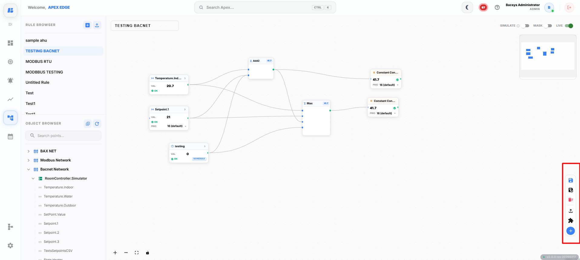
| Save Rules | Saves the current rule. |
| Save As Rule | Creates a duplicate of the current rule configuration with a new name, allowing modifications without altering the original rule. |
| Clear All Nodes | Deletes all nodes from the canvas. |
| Export Rules | Allows users to download and save all configured rules in a standardized file format (e.g., JSON or CSV) for backup, sharing, or transfer to another system. |
| Save Logic as Custom Block | Saves a group of connected logic blocks as a reusable custom block, allowing you to quickly reuse complex logic in other rules without rebuilding it from scratch. |
Open Libaray
When you click the “+” icon, it will open the library containing all the blocks.
##Math Block
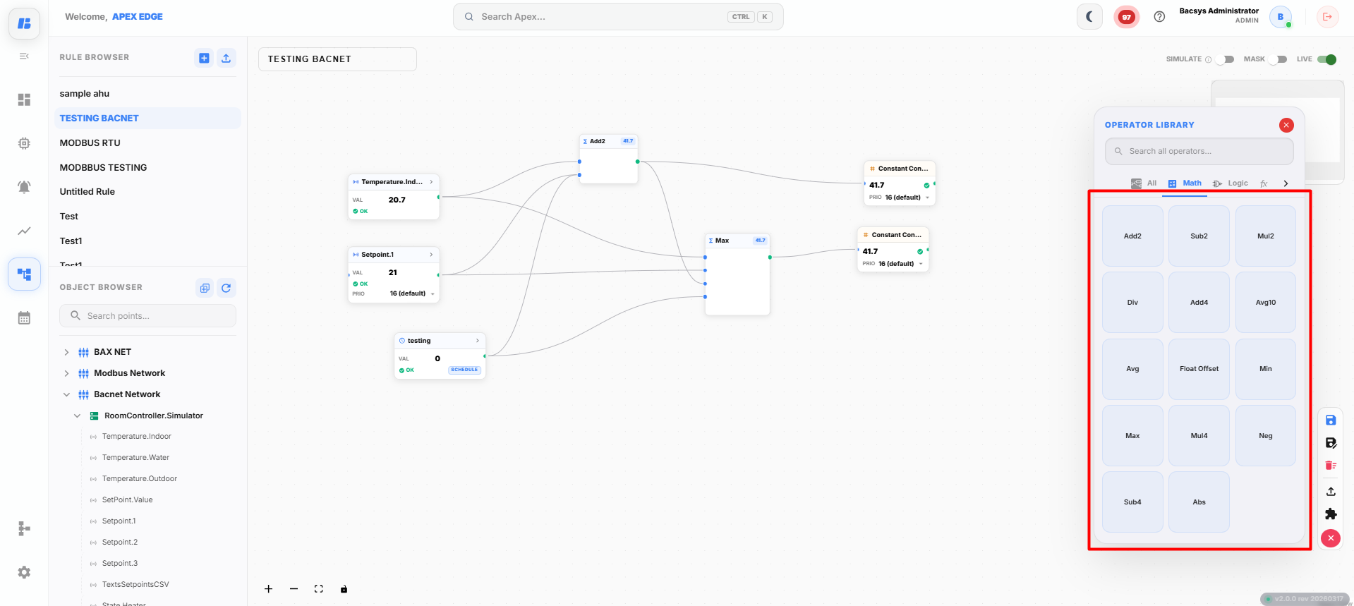
| Function | Description |
|---|---|
| Add2 | Adds two numbers together and returns the result. |
| Sub2 | Subtracts the second number from the first number and returns the result. |
| Mul2 | Multiplies two numbers together and returns the product. |
| Div | Divides the first number by the second number and returns the quotient (second number must not be zero). |
| Add4 | Adds four numbers together and returns the result. |
| Avg10 | Calculates and returns the average of ten numbers. |
| Avg | Calculates and returns the average of a list of numbers. |
| FloatOffset | Applies a specified float offset to a number and returns the adjusted value. |
| Min | Finds and returns the minimum value in a list of numbers. |
| Max | Finds and returns the maximum value in a list of numbers. |
| Mul4 | Multiplies four numbers together and returns the product. |
| Neg | Negates a number by multiplying it by -1 and returns the result. |
| Sub4 | Subtracts four numbers sequentially from the first number and returns the result. |
| Abs | Returns the absolute value of the input number |
| `` |
Logic Blocks
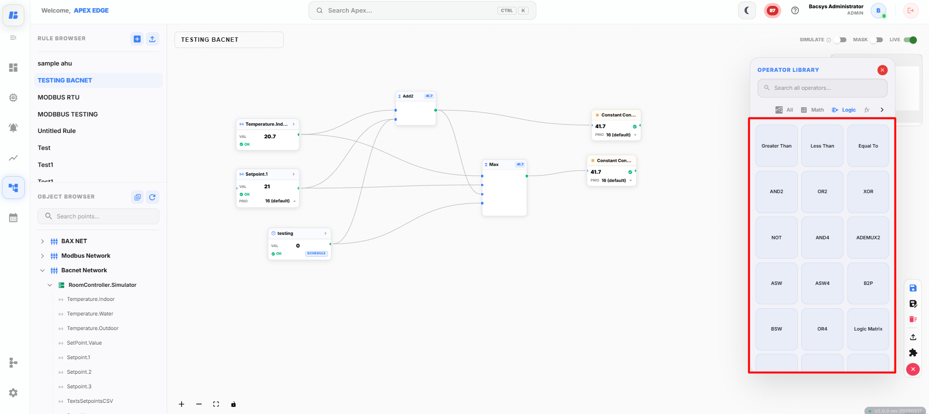
| Function | Description |
|---|---|
| Greater Than | Compares two numbers and returns TRUE if the first number is greater than the second, otherwise returns FALSE. |
| Less Than | Compares two numbers and returns TRUE if the first number is less than the second, otherwise returns FALSE. |
| Equal To | Compares two numbers and returns TRUE if both numbers are equal, otherwise returns FALSE. |
| AND2 | Performs a logical AND operation on two inputs and returns the result. |
| OR2 | Performs a logical OR operation on two inputs and returns the result. |
| XOR | Performs a logical XOR (exclusive OR) operation on two inputs and returns the result. |
| NOT | Performs a logical NOT operation on an input and returns the result. |
| AND4 | Performs a logical AND operation on four inputs and returns the result. |
| OR4 | Performs a logical OR operation on four inputs and returns the result. |
| ADEMUX2 | Demultiplexes a single input to two outputs based on a control signal. |
| ASW | Switches an analog signal based on a control input and returns the switched signal. |
| ASW4 | Switches four analog signals based on control inputs and returns the switched signals. |
| B2P | Converts a binary signal to a parallel format and returns the parallel signal. |
| BSW | Switches a binary signal based on a control input and returns the switched signal. |
| Logic Matrix | Evaluates multiple logical conditions using a matrix configuration and produces outputs based on the defined logic combinations. |
| Hysteresis | Introduces upper and lower threshold limits to prevent frequent switching when the input value fluctuates near a boundary. |
Function Blocks
The Function Blocks library provides advanced processing and control functions that enable users to implement automation logic, scheduling, notifications, data processing, and device control. These blocks are commonly used to build intelligent workflows and automate system operations.
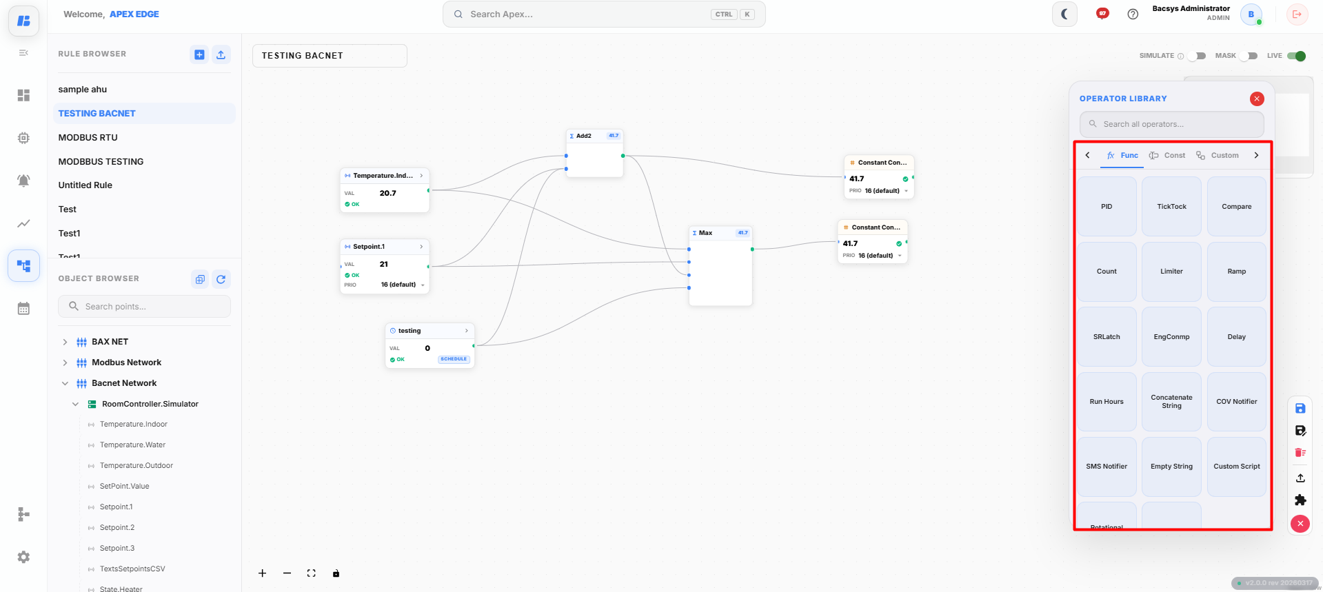
| Function | Description |
|---|---|
| PID | Implements a Proportional–Integral–Derivative (PID) controller to maintain a process variable at a desired setpoint. Commonly used in HVAC, temperature, pressure, and flow control applications. |
| Compare | Compares two input values and returns the comparison result, such as Equal, Greater Than, or Less Than. This block is commonly used for conditional decision-making within automation rules. |
| Count | Increments or decrements a counter based on input signals and returns the current count. It is useful for counting events, pulses, production cycles, or equipment operations. |
| Limiter | Restricts an input value within configured minimum and maximum limits. This block helps prevent values from exceeding safe operating ranges. |
| Ramp | Gradually increases or decreases an output value at a configured rate instead of changing instantly. It is commonly used for smooth equipment start-up and shutdown operations. |
| SRLatch | Implements a Set-Reset latch that maintains its output state until a reset signal is received. This block is commonly used for start/stop logic and maintaining equipment status. |
| EngComp | Calculates energy consumption using connected meter readings. This block is commonly used for energy monitoring, reporting, and consumption analysis. |
| Scheduler | Controls the execution of connected blocks based on configured dates, days, and time schedules. It is useful for automating equipment operation according to predefined schedules. |
| Delay | Delays the execution or transmission of signals by a specified duration. This block helps prevent immediate responses and is useful for sequencing operations. |
| RunHours | Calculates the total operating time of equipment based on its running status. This information is commonly used for preventive maintenance and runtime analysis. |
| Concatenate String | Combines two or more text strings into a single output. It is commonly used for generating messages, labels, or dynamic text values. |
| CoV Notifier | Sends a notification whenever a Change of Value (CoV) occurs on the monitored point. This block helps notify users when significant value changes are detected. |
| SMS Notifier | Sends SMS notifications when configured conditions or events occur. It is commonly used for alarm notifications and critical event reporting. |
| Empty String | Generates an empty text value that can be used as a placeholder or default string within automation logic. |
| Custom Script | Allows users to write and execute custom scripts for implementing advanced calculations, processing logic, or custom automation that cannot be achieved using standard blocks. |
| Rotational Load Sequencer | Rotates multiple connected loads according to a configured sequence to balance equipment runtime and distribute wear evenly across devices. This block is commonly used for pumps, fans, compressors, and similar equipment. |
PID Block
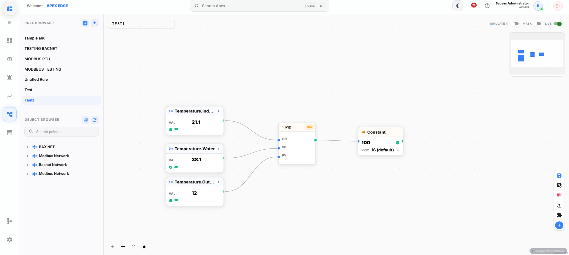
The PID (Proportional–Integral–Derivative) block is used to automatically control a process variable by comparing the measured value with a configured setpoint and generating an appropriate output. It is commonly used for temperature, pressure, flow, and other control applications.
Adding the PID Block
-
Open the Rules module.
-
Create a new rule or open an existing rule.
-
Click the + icon and open the Function category.
-
Drag and drop the PID block onto the canvas.
-
Right-click the PID block to open the configuration window.
-
Configure the required parameters (KP, KI, KD, MIN, and MAX). Enable Reverse PID if required.
-
Click Save to apply the configuration.
PID Connections
| Connection | Description |
|---|---|
| ON | Enables or disables the PID controller. |
| SP | Specifies the desired setpoint value. |
| PV | Represents the measured process value. |
| Output | Returns the calculated control output. |
Configuring the PID Block
Double-click the PID block to open the configuration window.
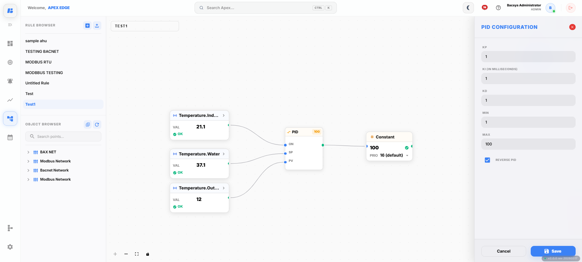
| Parameter | Description |
|---|---|
| KP | Sets the proportional gain. |
| KI | Sets the integral gain. |
| KD | Sets the derivative gain. |
| MIN | Defines the minimum output value. |
| MAX | Defines the maximum output value. |
| Reverse PID | Enables reverse control action when required. |
Click Save to apply the configuration.
TickTock Block
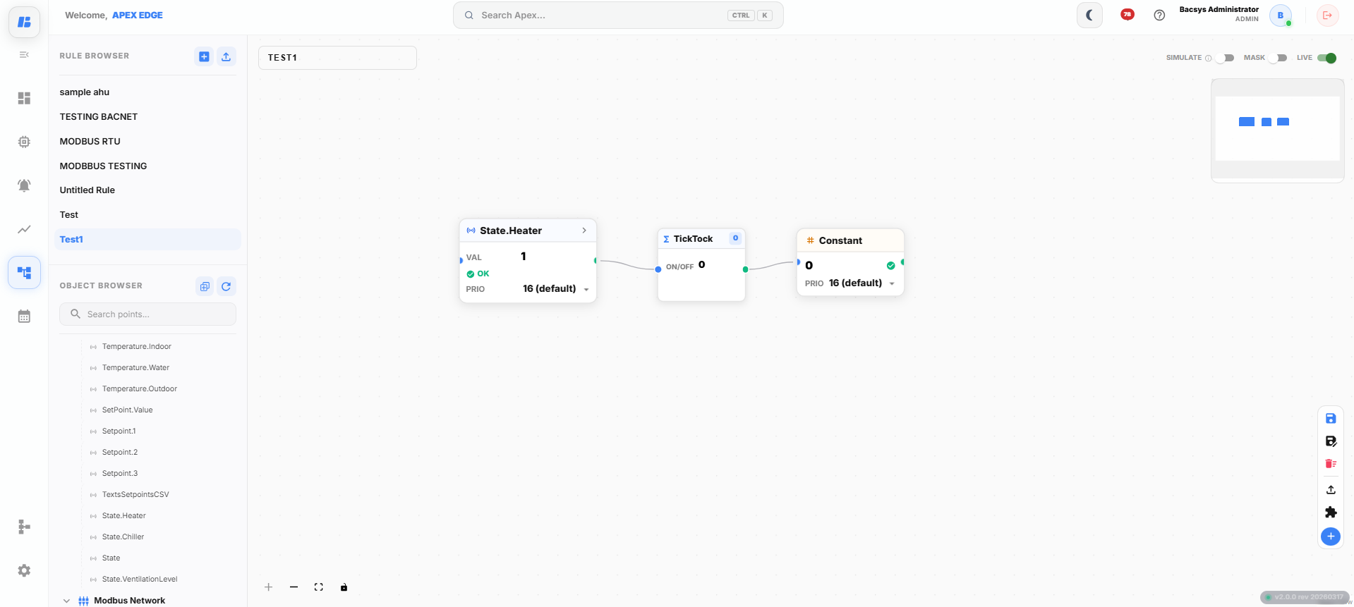
The TickTock block generates periodic output signals based on the configured time interval. It is commonly used to create repeating events, periodic triggers, and timed control operations within a rule.
Adding the TickTock Block
-
Open the Rules module.
-
Create a new rule or open an existing rule.
-
Click the + icon and open the Function category.
-
Drag and drop the TickTock block onto the canvas.
-
Connect the ON/OFF input to the required control point and connect the output to the destination point or block.
-
Right-click the TickTock block to open the TickTock Configuration window.
-
Configure the required parameters and click Save.
TickTock Connections
| Connection | Description |
|---|---|
| ON/OFF | Enables or disables the TickTock block. |
| Output | Generates periodic output signals based on the configured timing values. |
Configuring the TickTock Block
Double-click or right-click the TickTock block to open the configuration window.
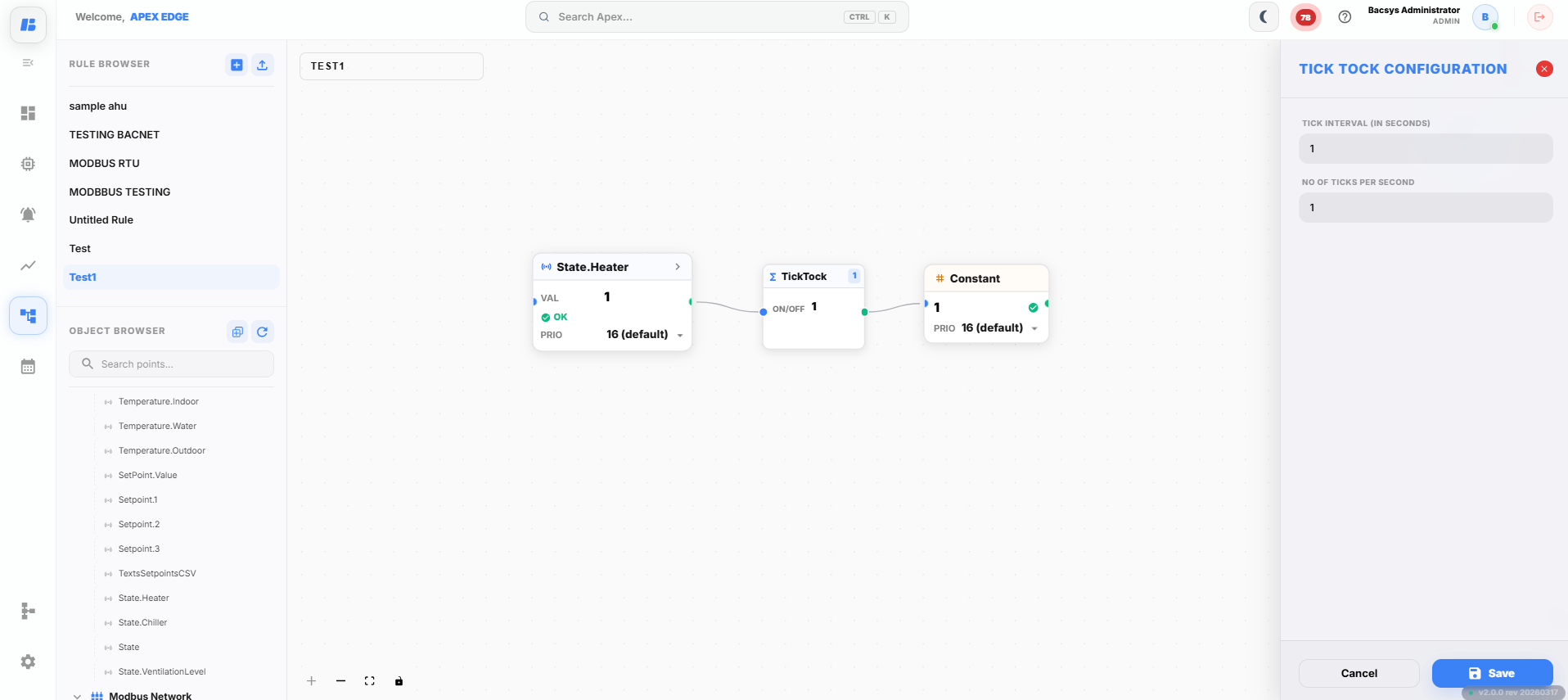
| Parameter | Description |
|---|---|
| Tick Interval (In Seconds) | Specifies the time interval between generated ticks. |
| No of Ticks Per Second | Specifies the number of output ticks generated during each second. |
Click Save to apply the configuration.
Count Block
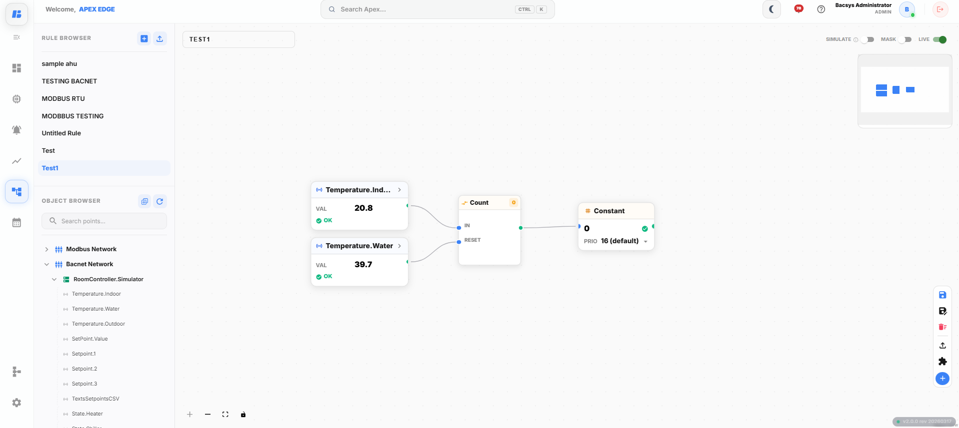
The Count block counts events based on the configured counting direction. It can increment or decrement the count value when the input changes and is commonly used for event counting, production tracking, and monitoring equipment operations.
Adding the Count Block
-
Open the Rules module.
-
Create a new rule or open an existing rule.
-
Click the + icon and open the Function category.
-
Drag and drop the Count block onto the canvas.
-
Connect the required input and output points.
-
Double-click the Count block to open the Count Configuration window.
-
Configure the required parameters and click Save.
Count Connections
| Connection | Description |
|---|---|
| Input | Receives the signal to be counted. |
| Output | Returns the current count value. |
Configuring the Count Block
Double-click the Count block to open the configuration window.
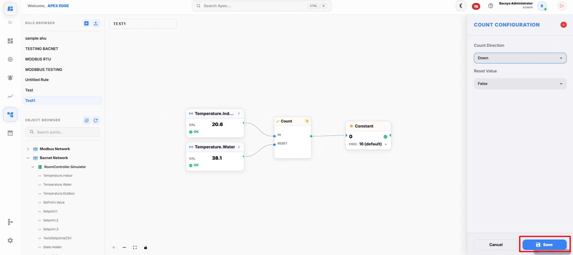
| Parameter | Description |
|---|---|
| Count Direction | Selects the counting direction. Available options are Up, Down, or Any Changes. |
| Reset Value | Specifies the value to which the counter resets. |
| Reset | Enables or disables the reset operation by selecting True or False. |
Click Save to apply the configuration.
Limiter Block
The Limiter block restricts the output value within a configured range. If the input exceeds the configured limits, the output is automatically limited to the defined minimum or maximum value.
Adding the Limiter Block
-
Open the Rules module.
-
Create a new rule or open an existing rule.
-
Click the + icon and open the Function category.
-
Drag and drop the Limiter block onto the canvas.
-
Connect the required input and output points.
-
Double-click the Limiter block to open the Limiter Configuration window.
-
Configure the High Limit and Low Limit values.
-
Click Save to apply the configuration.
Limiter Connections
| Connection | Description |
|---|---|
| Input | Receives the value to be limited. |
| Output | Returns the value after applying the configured limits. |
Configuring the Limiter Block
Double-click the Limiter block to open the configuration window.
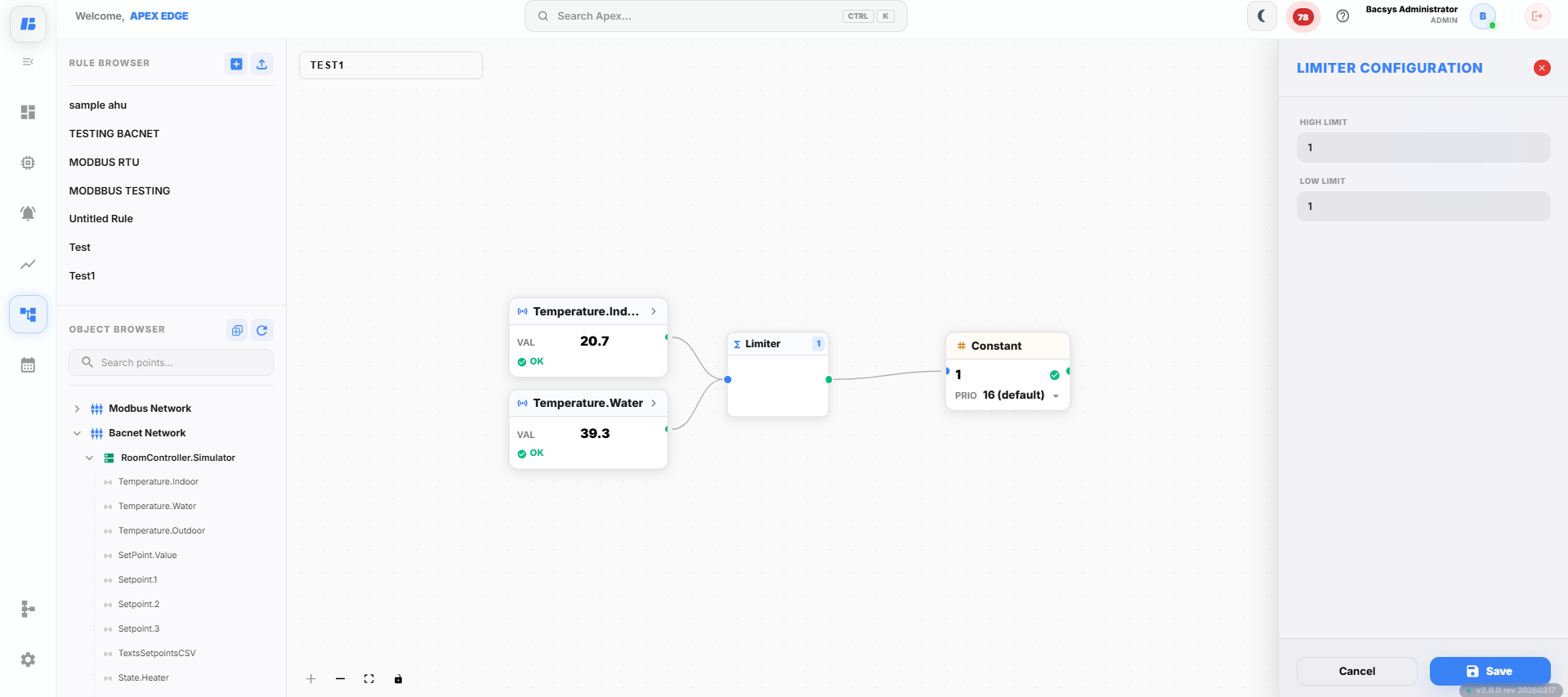
| Parameter | Description |
|---|---|
| High Limit | Specifies the maximum value allowed at the output. Any input above this value is limited to the High Limit. |
| Low Limit | Specifies the minimum value allowed at the output. Any input below this value is limited to the Low Limit. |
Click Save to apply the configuration.
Ramp Block
The Ramp block gradually increases or decreases the output value between the configured minimum and maximum values over a specified period. It is commonly used to provide smooth transitions and prevent sudden changes in control signals.
Adding the Ramp Block
-
Open the Rules module.
-
Create a new rule or open an existing rule.
-
Click the + icon and open the Function category.
-
Drag and drop the Ramp block onto the canvas.
-
Connect the required input and output points.
-
Double-click the Ramp block to open the Ramp Configuration window.
-
Configure the required parameters.
-
Click Save to apply the configuration.
Ramp Connections
| Connection | Description |
|---|---|
| Input | Receives the value to be ramped. |
| Output | Returns the gradually changing output value. |
Configuring the Ramp Block
Double-click the Ramp block to open the configuration window.
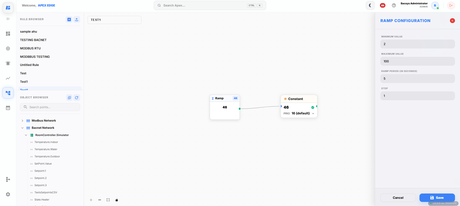
| Parameter | Description |
|---|---|
| Minimum Value | Specifies the lowest output value of the ramp. |
| Maximum Value | Specifies the highest output value of the ramp. |
| Ramp Period | Defines the time taken for the output to change from the minimum value to the maximum value. |
| Step | Specifies the increment or decrement applied to the output during each ramp interval. |
Click Save to apply the configuration.
SRLatch Block
The SRLatch block is used to maintain an output state until it is reset. It is commonly used for start/stop control, equipment latching, and maintaining the status of a device.
Adding the SRLatch Block
-
Open the Rules module.
-
Create a new rule or open an existing rule.
-
Click the + icon and open the Function category.
-
Drag and drop the SRLatch block onto the canvas.
-
Connect the required input and output points.
-
Double-click or right-click the SRLatch block to open the SRLatch Configuration window.
-
Configure the Reset Value.
-
Click Save to apply the configuration.
SRLatch Connections
| Connection | Description |
|---|---|
| Set (S) | Sets the output to the active state. |
| Reset (R) | Resets the output to the configured reset value. |
| Output | Returns the current latched output state. |
Configuring the SRLatch Block
Double-click or right-click the SRLatch block to open the configuration window.
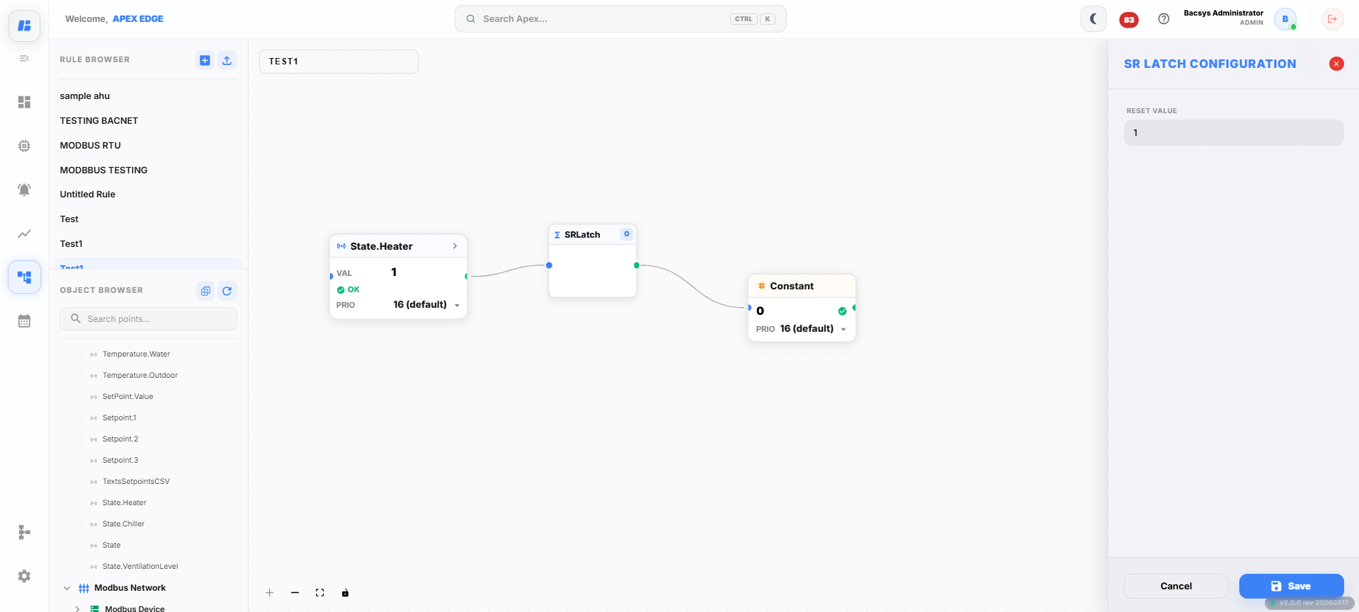
| Parameter | Description |
|---|---|
| Reset Value | Specifies the value assigned to the output when the Reset input is activated. |
Click Save to apply the configuration.
SRLatch Logic
The SRLatch block stores the output state when the Set input is activated. The output remains in the latched state until the Reset input is triggered, at which point the output changes to the configured Reset Value.
Energy Consumption Block
The Energy Consumption block calculates and displays energy consumption over a selected time interval. It is commonly used for monitoring and analyzing energy usage on an hourly, daily, weekly, monthly, or yearly basis.
Adding the Energy Consumption Block
-
Open the Rules module.
-
Create a new rule or open an existing rule.
-
Click the + icon and open the Function category.
-
Drag and drop the Energy Consumption block onto the canvas.
-
Connect the required input and output points.
-
Right-click the Energy Consumption block to open the Energy Consumption Configuration window.
-
Select the required calculation interval.
-
Click Save to apply the configuration.
Energy Consumption Connections
| Connection | Description |
|---|---|
| Input | Receives the energy meter or consumption value. |
| Output | Returns the calculated energy consumption for the selected interval. |
Configuring the Energy Consumption Block
Right-click the Energy Consumption block to open the configuration window.
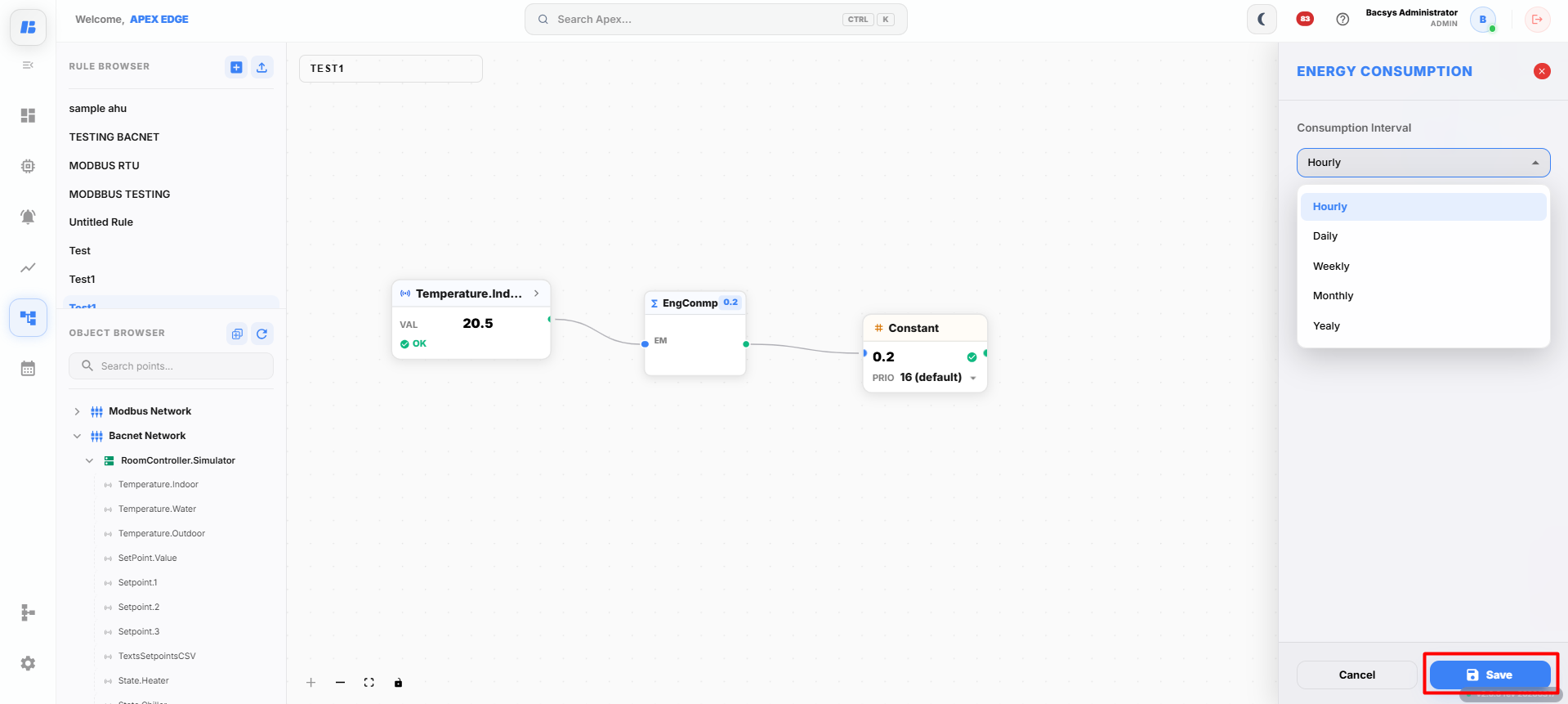
| Parameter | Description |
|---|---|
| Hourly | Calculates energy consumption for every hour. |
| Daily | Calculates energy consumption for each day. |
| Weekly | Calculates energy consumption for each week. |
| Monthly | Calculates energy consumption for each month. |
| Yearly | Calculates energy consumption for each year. |
Click Save to apply the configuration.
Delay Block
The Delay block postpones the execution of an output signal by a specified duration. It is commonly used to introduce a time delay before triggering the next operation in a rule.
Adding the Delay Block
-
Open the Rules module.
-
Create a new rule or open an existing rule.
-
Click the + icon and open the Function category.
-
Drag and drop the Delay block onto the canvas.
-
Connect the required input and output points.
-
Right-click the Delay block to open the Delay Configuration window.
-
Configure the required delay duration.
-
Click Save to apply the configuration.
Delay Connections
| Connection | Description |
|---|---|
| Input | Receives the signal to be delayed. |
| Output | Returns the input signal after the configured delay period. |
Configuring the Delay Block
Right-click the Delay block to open the configuration window.
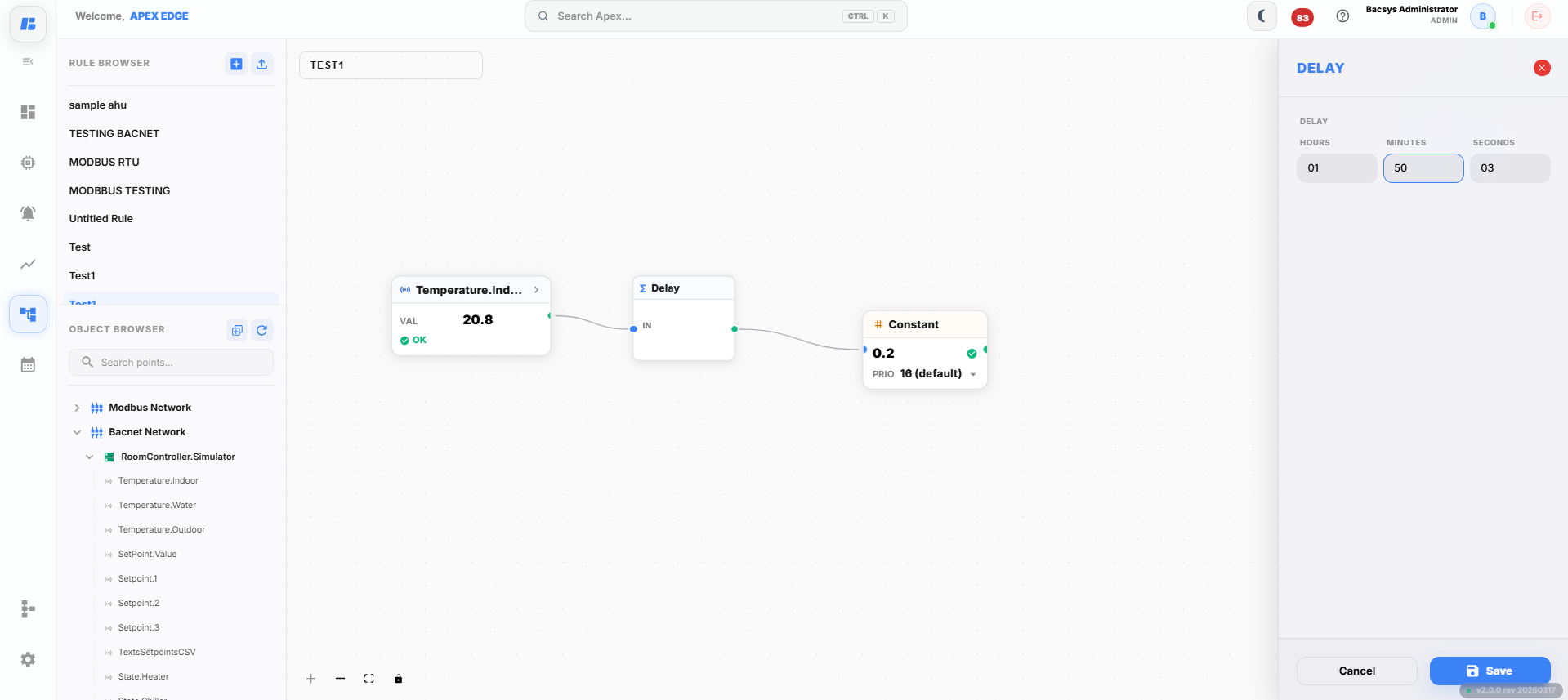
| Parameter | Description |
|---|---|
| Hours | Specifies the delay duration in hours. |
| Minutes | Specifies the delay duration in minutes. |
| Seconds | Specifies the delay duration in seconds. |
Click Save to apply the configuration.
Custom Script Editor
The Custom Script Editor block allows users to write and execute custom scripts for implementing advanced automation logic, calculations, and data processing that cannot be achieved using standard function blocks.
Adding the Custom Script Editor
-
Open the Rules module.
-
Create a new rule or open an existing rule.
-
Click the + icon and open the Function category.
-
Drag and drop the Custom Script Editor block onto the canvas.
-
Connect the required input and output points.
-
Double-click or right-click the Custom Script Editor block to open the script editor.
-
Write or modify the required script.
-
Click Save to apply the script.
Custom Script Editor Connections
| Connection | Description |
|---|---|
| Input | Receives values that are used within the custom script. |
| Output | Returns the value calculated or processed by the script. |
Using the Custom Script Editor
Double-click or right-click the Custom Script Editor block to open the script editor.
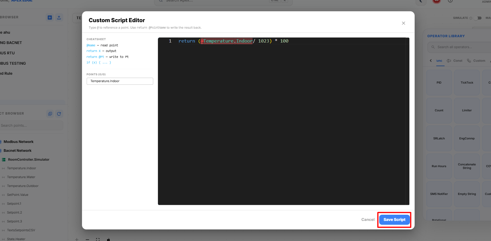
The editor allows you to write and modify custom logic according to your application requirements.
Click Save to apply the script.
RLS Block
The RLS (Rotational Load Sequencing) block is used to control and sequence multiple loads efficiently. It helps distribute operating time among connected loads and supports automatic or manual sequencing.
Adding the RLS Block
-
Open the Rules module.
-
Create a new rule or open an existing rule.
-
Click the + icon and open the Function category.
-
Drag and drop the RLS block onto the canvas.
-
Connect the required input and output points.
-
Right-click the RLS block to open the RLS Configuration window.
-
Configure the required parameters.
-
Click Save to apply the configuration.
RLS Connections
| Connection | Description |
|---|---|
| Input | Receives the control signal for load sequencing. |
| Output | Controls the connected loads based on the configured sequence. |
Configuring the RLS Block
Right-click the RLS block to open the configuration window.
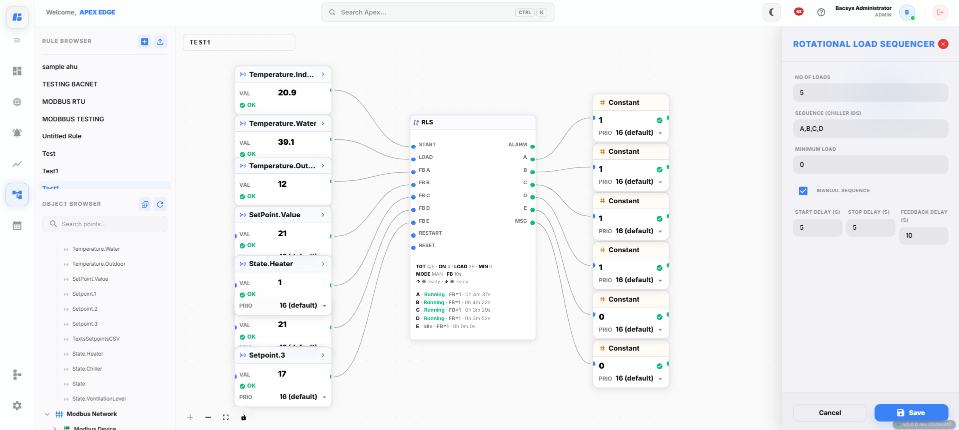
| Parameter | Description |
|---|---|
| No of Loads | Specifies the total number of loads to be controlled. |
| Sequence | Defines the order in which the loads operate. |
| Minimum Load | Specifies the minimum number of loads that must remain active. |
| Manual Sequence | Enables manual sequencing of loads when the checkbox is selected. |
| Start Delay | Specifies the delay before starting the next load. |
| Stop Delay | Specifies the delay before stopping a load. |
| Feedback Delay | Specifies the waiting time for load feedback before proceeding to the next operation. |
Click Save to apply the configuration.
Alarm Block
The Alarm block is used to generate alarms when configured conditions are met. It allows users to define an alarm message, configure the notification interval, and assign a priority level for the alarm.
Adding the Alarm Block
-
Open the Rules module.
-
Create a new rule or open an existing rule.
-
Click the + icon and open the Function category.
-
Drag and drop the Alarm block onto the canvas.
-
Connect the required input and output points.
-
Right-click the Alarm block to open the Alarm Configuration window.
-
Configure the required parameters.
-
Click Save to apply the configuration.
Alarm Connections
| Connection | Description |
|---|---|
| Input | Receives the signal or condition used to trigger the alarm. |
| Output | Generates the configured alarm when the trigger condition is satisfied. |
Configuring the Alarm Block
Right-click the Alarm block to open the configuration window.
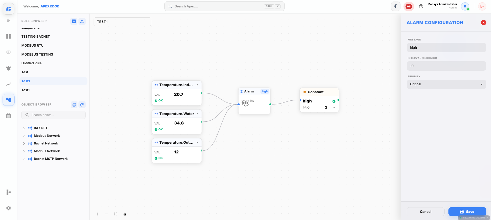
| Parameter | Description |
|---|---|
| Message | Specifies the alarm message displayed when the alarm is triggered. |
| Interval | Specifies the time interval between consecutive alarm notifications. |
| Priority | Specifies the priority level of the alarm. Available options are High, Medium, and Low. |
Click Save to apply the configuration.
Creating and Using a Custom Block
A Custom Block allows you to save a group of connected logic blocks as a reusable block. This helps reduce development time and simplifies the creation of complex automation logic.
Creating a Custom Block
-
Click Add New Rule to create a new rule.
-
Build the required logic by adding and connecting the necessary blocks on the canvas.
-
Select the group of connected logic blocks that you want to reuse.
-
Click Save Logic as Custom Block.
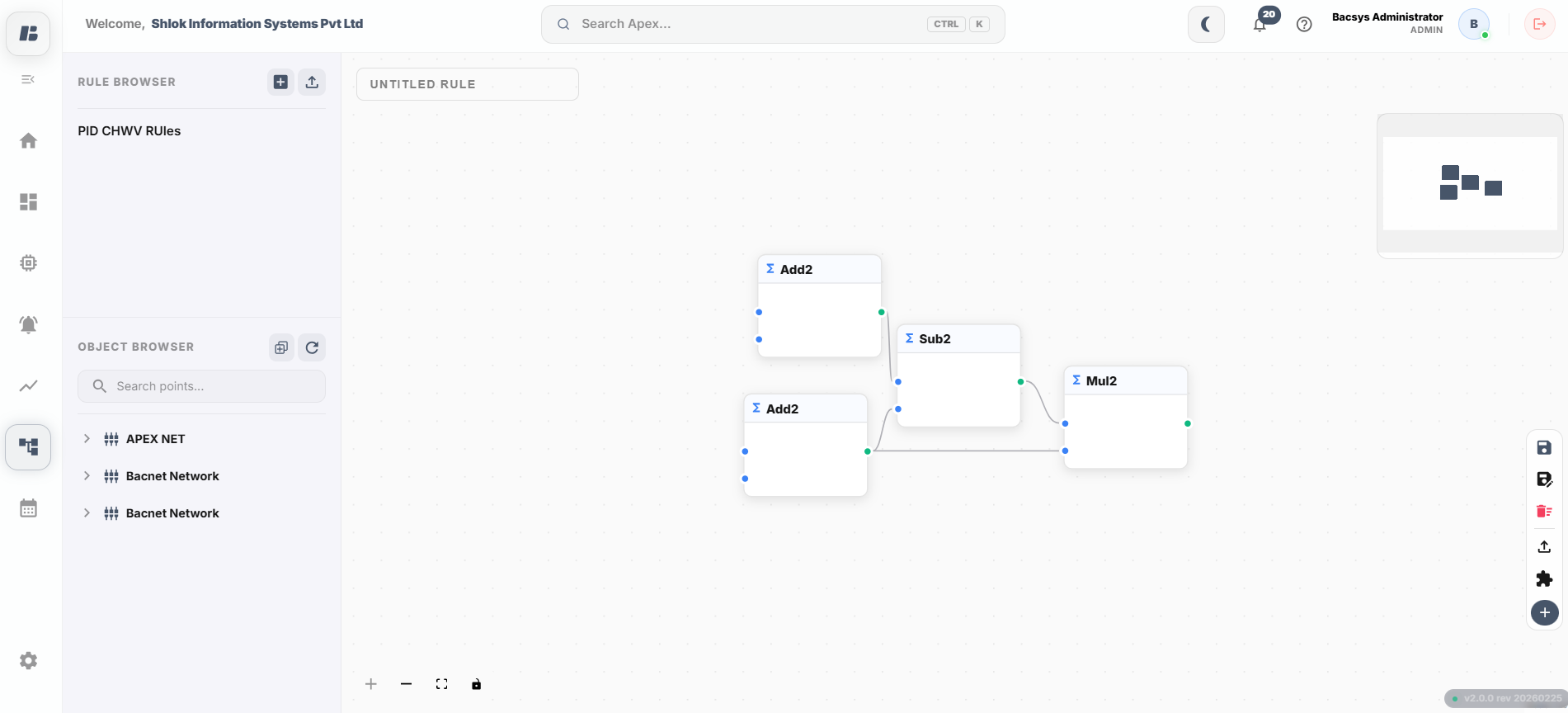
-
Enter a Name for the custom block.
-
Click Save.
-
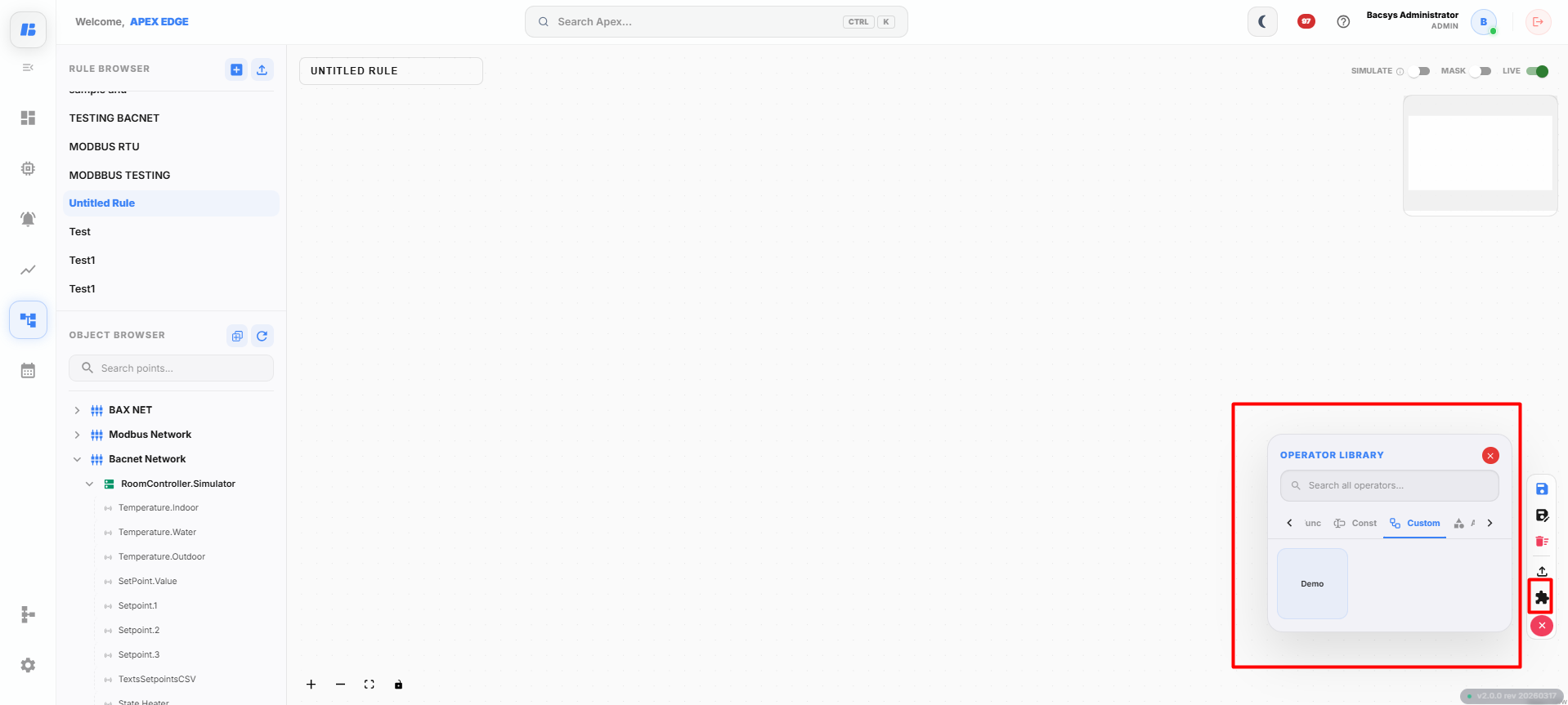
Open the Custom Blocks library.
-
The saved custom block appears in the library with the specified name.
-
Drag and drop the custom block onto the canvas whenever it is required.
Configuring the Custom Block
Right-click the Custom Block on the canvas to open the configuration window.
| Parameter | Description |
|---|---|
| Label | Specifies the display name for the custom block parameter. |
| Value | Specifies the value assigned to the corresponding label. |
Click Save to apply the configuration.
Advanced
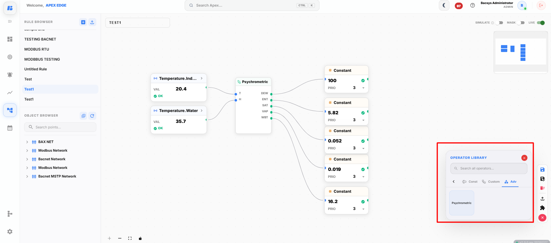
| Advanced Function | Description |
|---|---|
| Psychrometric | Calculates air properties such as dry bulb temperature, wet bulb temperature, relative humidity, dew point, and enthalpy based on the provided input conditions. It is commonly used in HVAC and environmental control applications. |
Delete a Rule
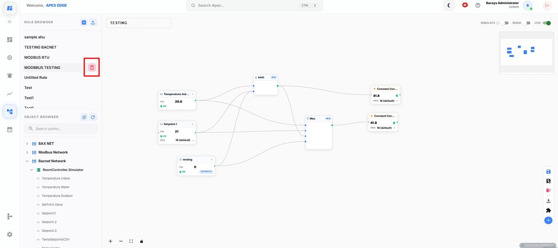
To delete an existing rule:
-
Open the Rules module.
-
Select the rule you want to delete from the Rules browser.
-
Click the Delete icon.
-
A confirmation dialog will appear.
-
Click Yes to permanently delete the selected rule.
Note: Once deleted, the rule cannot be recovered unless it has been exported previously.
Rename a Rule
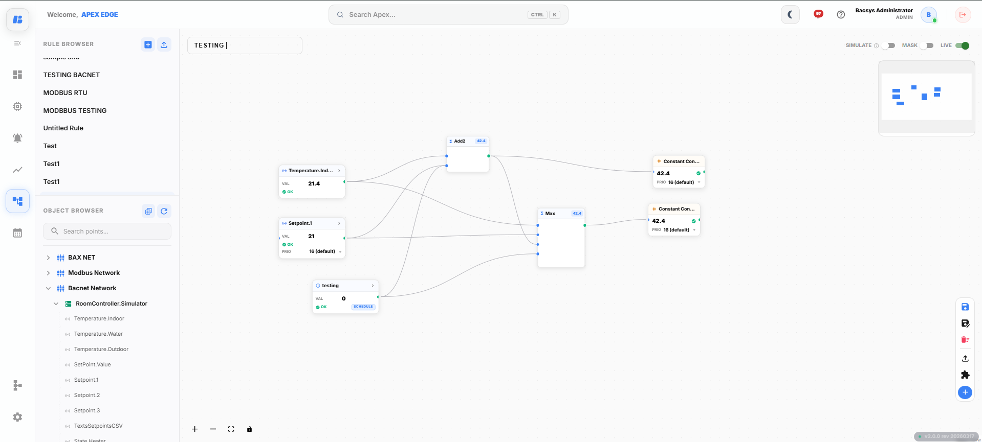
To rename an existing rule:
-
Open the Rules module.
-
Select the rule you want to rename from the Rules browser.
-
Click the rule name or select the Rename option.
-
Enter the new rule name.
-
Click Save to apply the changes.
Export a Rule
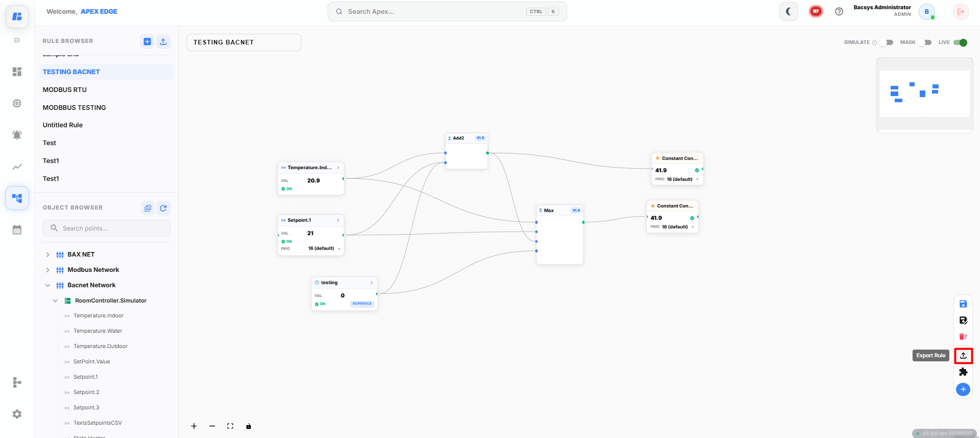
To export a rule:
-
Open the Rules module.
-
Select the rule you want to export.
-
Click the Export Rule icon.
-
Choose the location where you want to save the exported file.
-
Click Save to export the rule.
Note: The exported rule can be used as a backup or shared with another system.
Import a Rule
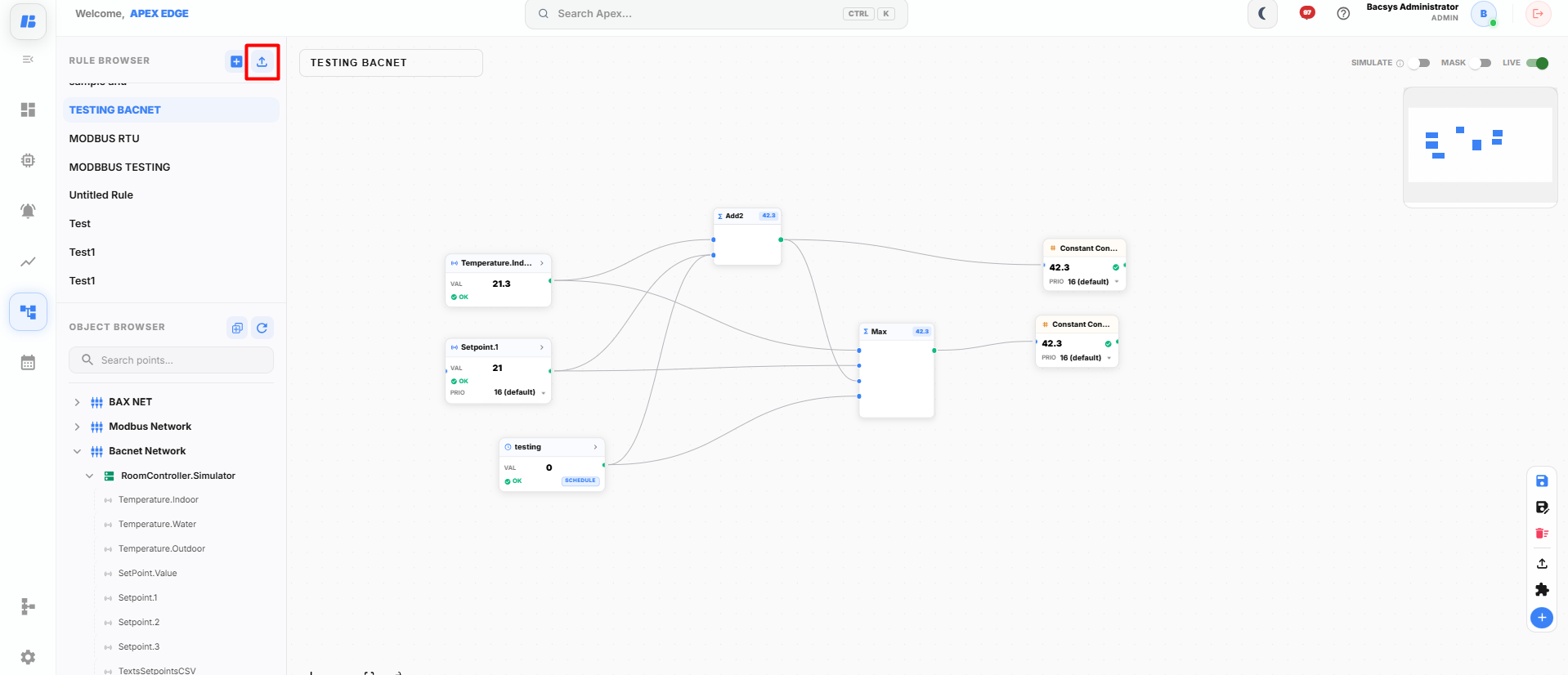
To import a previously exported rule:
-
Open the Rules module.
-
Click the Import Rule icon.
-
Browse and select the exported rule file.
-
Click Open or Import.
-
The imported rule will be added to the Rules browser and can be edited or executed like any other rule.