

Devices
The Device Module is used to onboard Apex controllers to the Bacsys Cloud Platform. It enables users to add networks, devices, and points from connected Apex controllers to the platform seamlessly.
Once onboarded, each point can be configured, monitored, and optimized directly through the Bacsys Cloud interface. The platform supports connecting and managing multiple Apex controllers simultaneously, providing centralized visibility and control over all associated devices and networks.
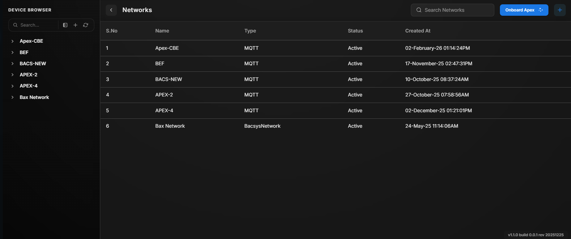 Devices module
Accessing the Device Module
- Click on the Device icon on the main menu.
- Click on (>) button to Expand or (<) button to collapse the browser menu.
- The browser menu lists all the networks, devices and points.
Network
Creating a Network
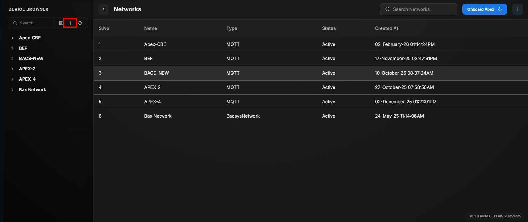 Adding a new network
Creating a Network
Step 1:
- Click on the + (Add) icon to create a new network.
Step 2:
- The Add Network configuration page will be displayed.
- Choose the required protocol.
- Select MQTT as the network type.
Supported Network Protocol
| Protocol | Applications | Technical Information |
|---|---|---|
| MQTT | MQTT protocol is widely used in industrial automation for device communication. | Implements a client-based architecture where APEX devices act as clients. |
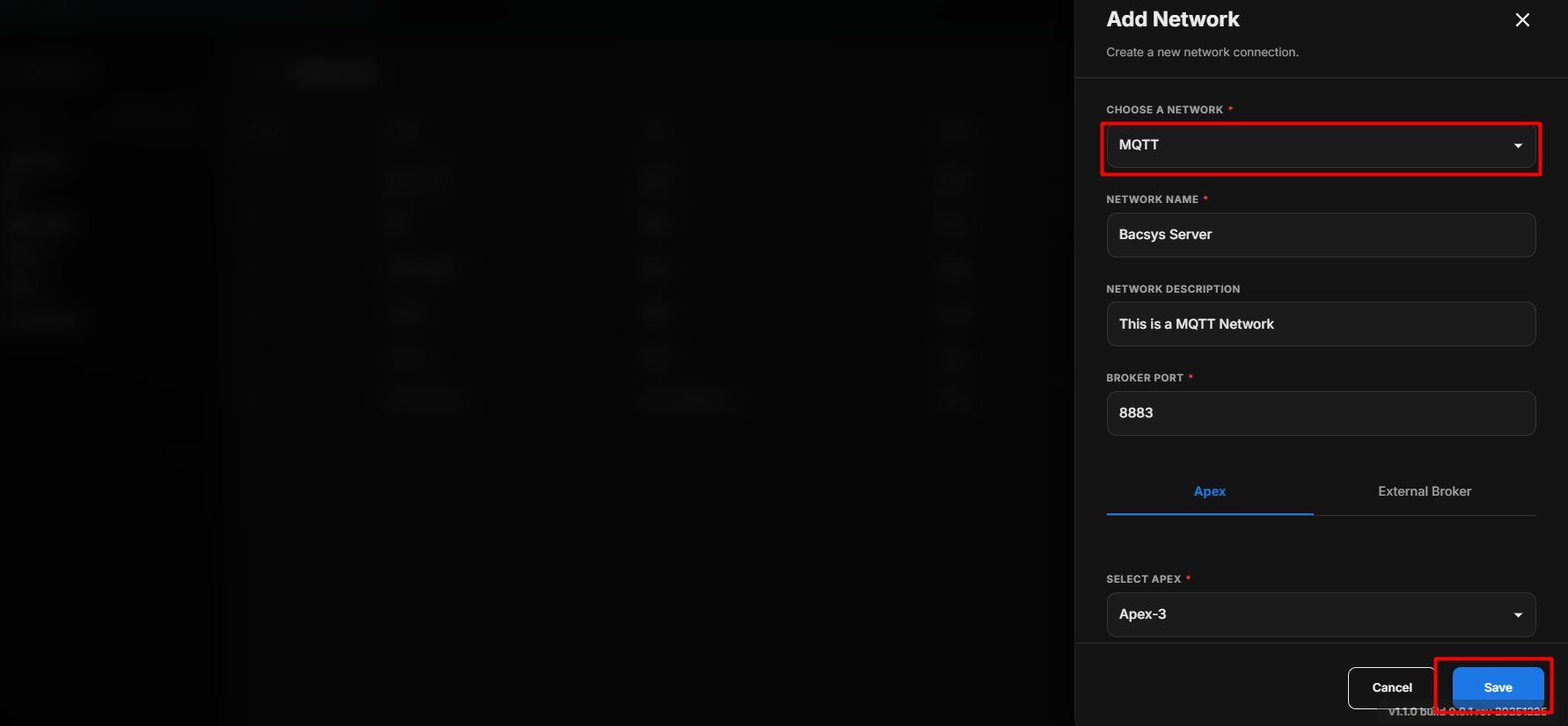
- Once the type of network is selected, you should fill in the parameters of the network in the given fields.
Network Configuration Fields
| Field | Description |
|---|---|
| Choose Network | Allows users to select the type of network to be configured. |
| Network Name | Specifies the unique name assigned to the network. |
| Network Description | Provides additional details or purpose of the network configuration. |
| Broker Port | Defines the communication port used by the broker for network connectivity. |
| Select Apex | Allows users to select the required Apex controller for the network. |
| External Broker | Option to configure an external broker connection. |
| Broker Host | Specifies the hostname or IP address of the external broker. |
| Parent Topic | Defines the main MQTT topic under which messages are published or subscribed. |
| Select Auth Scheme | Allows users to choose the authentication method (e.g., Username/Password, TLS, etc.). |
| Save | Saves the configured network settings and applies them to the system. |
- After filling all the details of the network, you can add the respective network by clicking Save button or cancle it by clicking Cancel button given below.
- The created network will be displayed in the Network listing pane adjacent to the device browser.
Managing a Network
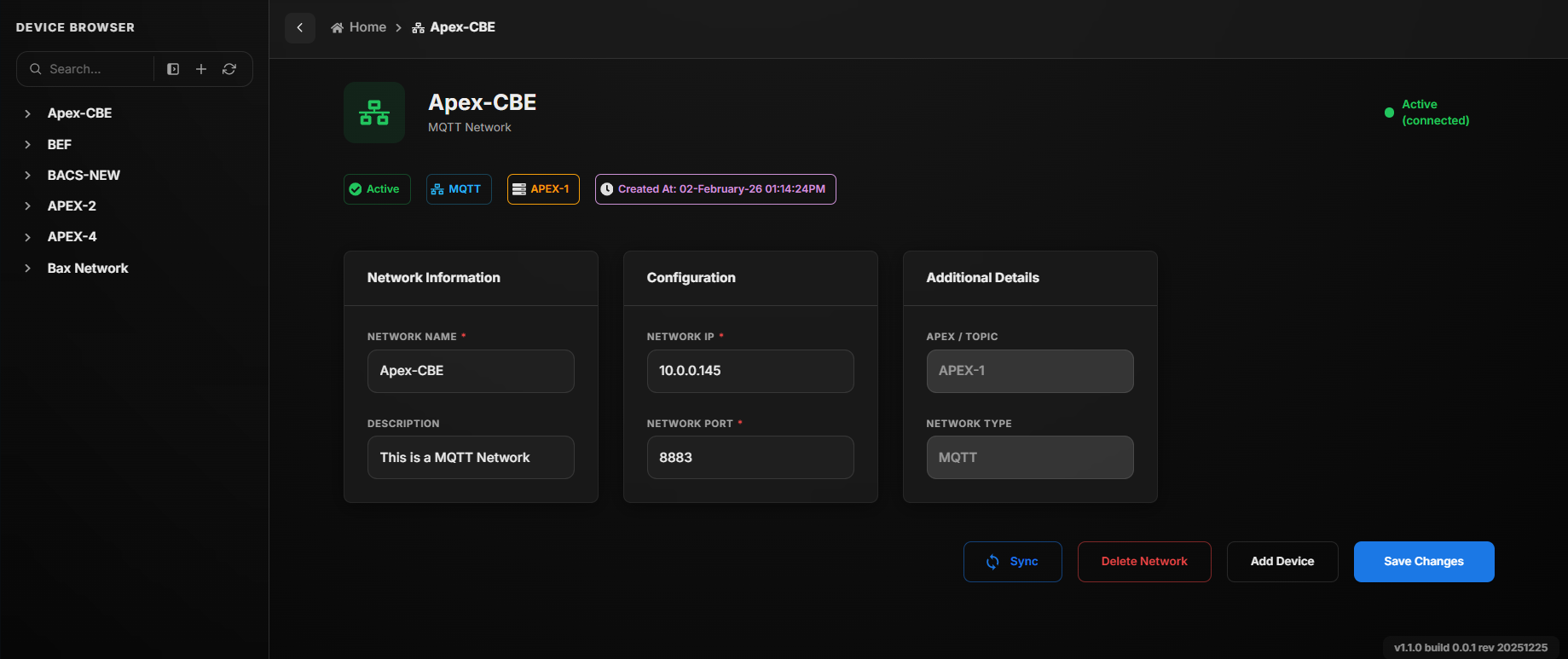 Network Properties Screen
Sync Network
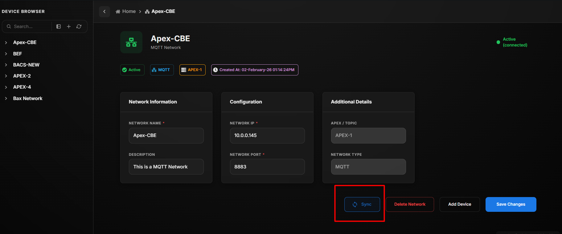 Sync
The Sync option allows users to synchronize data from the controller.
When the Sync button is clicked:
- The system connects to the configured controller.
- Network data, devices, and associated points are synchronized.
- Any newly detected devices or updates from the controller are reflected in the system.
This ensures that the platform remains updated with the latest configuration from the controller.
Delete Network
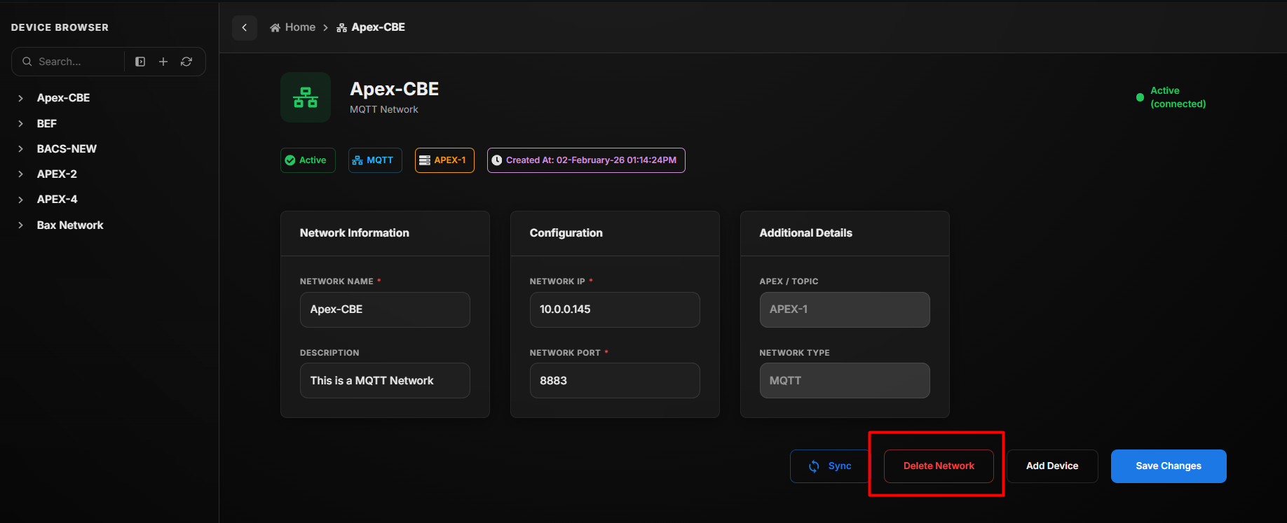 Delete the Network
The Delete Network option allows users to remove a configured network from the system.
When the Delete Network button is clicked:
- The selected network is permanently removed from the system.
- All associated devices and points under that network are also removed.
- The network will no longer appear in the Network Listing Pane.
Warning: This action cannot be undone. Ensure confirmation before deleting a network.
Add Device
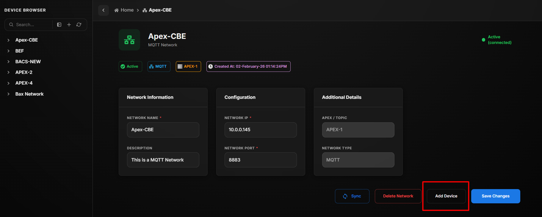 Add Device
When the Add Device button is clicked:
- A pop-up window appears.
- The pop-up provides options to:
- Discover Device
- Create Virtual Device
Discover Device
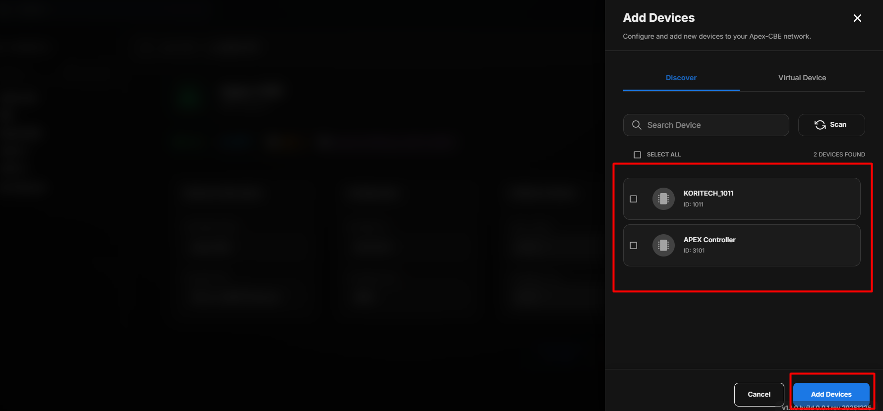 Device Discovery
The Discover option allows automatic detection of available devices.
- When Scan is clicked, the system scans for available devices connected to the network.
- All detected devices are displayed in a list.
- Users can directly select and add the discovered devices to the system.
Virtual Device
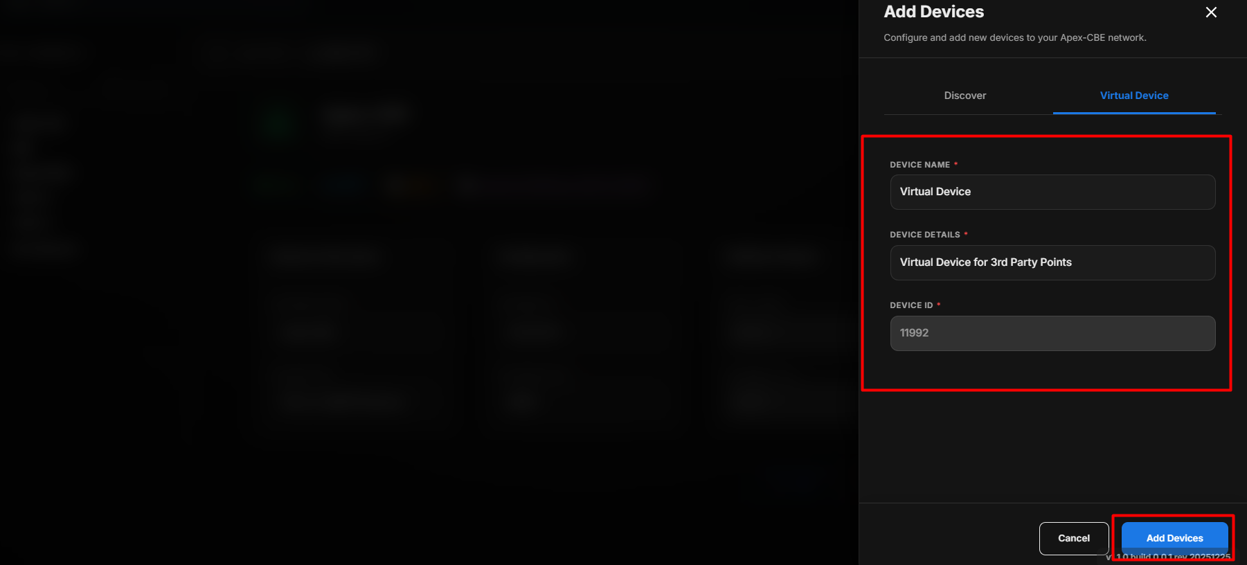 VirtuvalDevice
The Virtual Device option allows users to manually create a device.
- Users must enter the required details such as:
- Device Name
- Device Details
- Device ID
- After entering the details, click Add Device.
- The virtual device will then be added to the system.
Save Changes
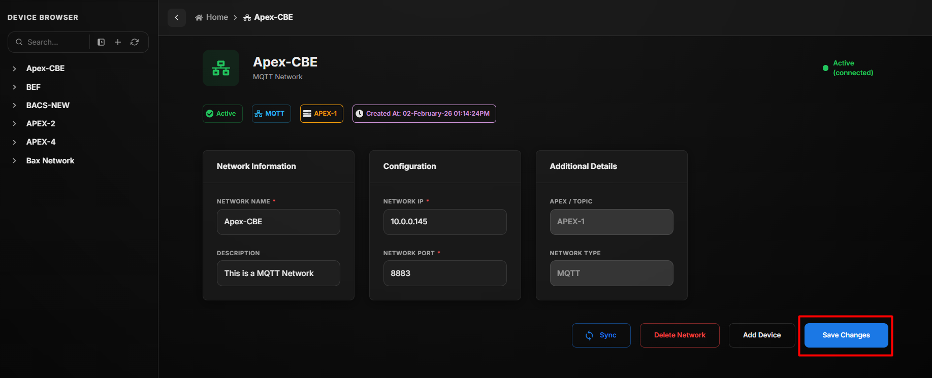 Device Save Changes
The Save Changes option allows users to store the modifications made to the current configuration.
When the Save Changes button is clicked:
- All newly added items are saved.
- Any updates or edits to existing configurations are applied.
- Deleted items are permanently removed (if applicable).
- The system confirms that the changes have been successfully saved.
Point Properties
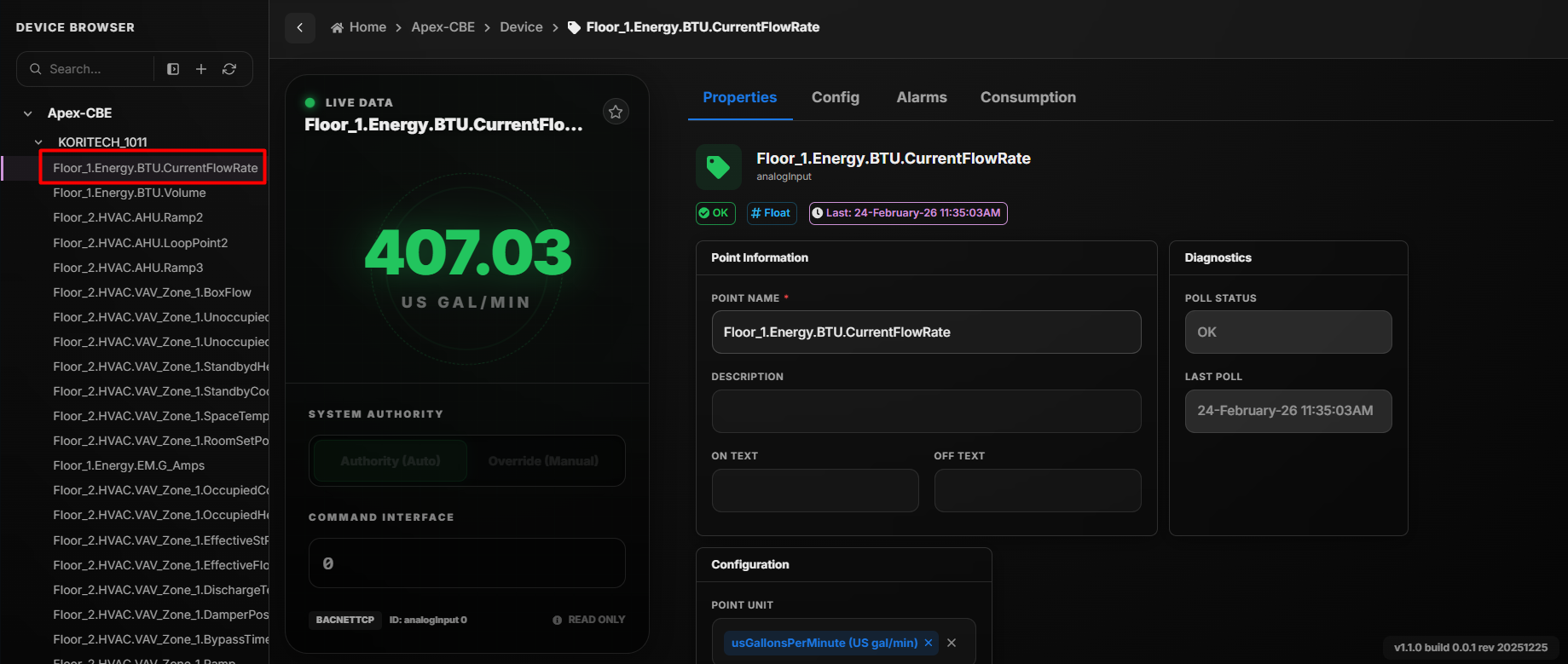 Device Points
Point Information
| Field | Description |
|---|---|
| Point Name | Displays the name assigned to the selected point. |
| Point Description | Provides additional details or explanation about the point. |
| ON Text | Defines the display text shown when the point status is ON (for digital points). |
| OFF Text | Defines the display text shown when the point status is OFF (for digital points). |
Diagnostics
| Field | Description |
|---|---|
| Poll Status | Indicates whether the point is currently being polled successfully. |
| Last Poll | Displays the date and time when the point was last successfully polled. |
Configuration
| Field | Description |
|---|---|
| Point Unit | Specifies the measurement unit of the point (e.g., °C, %, kW, etc.). |
| Address | Defines the communication address used to identify the point within the device. |
| Data Type | Specifies the type of data (e.g., Analog, Digital, Integer, Float, Boolean). |
Point Configuration Tab:
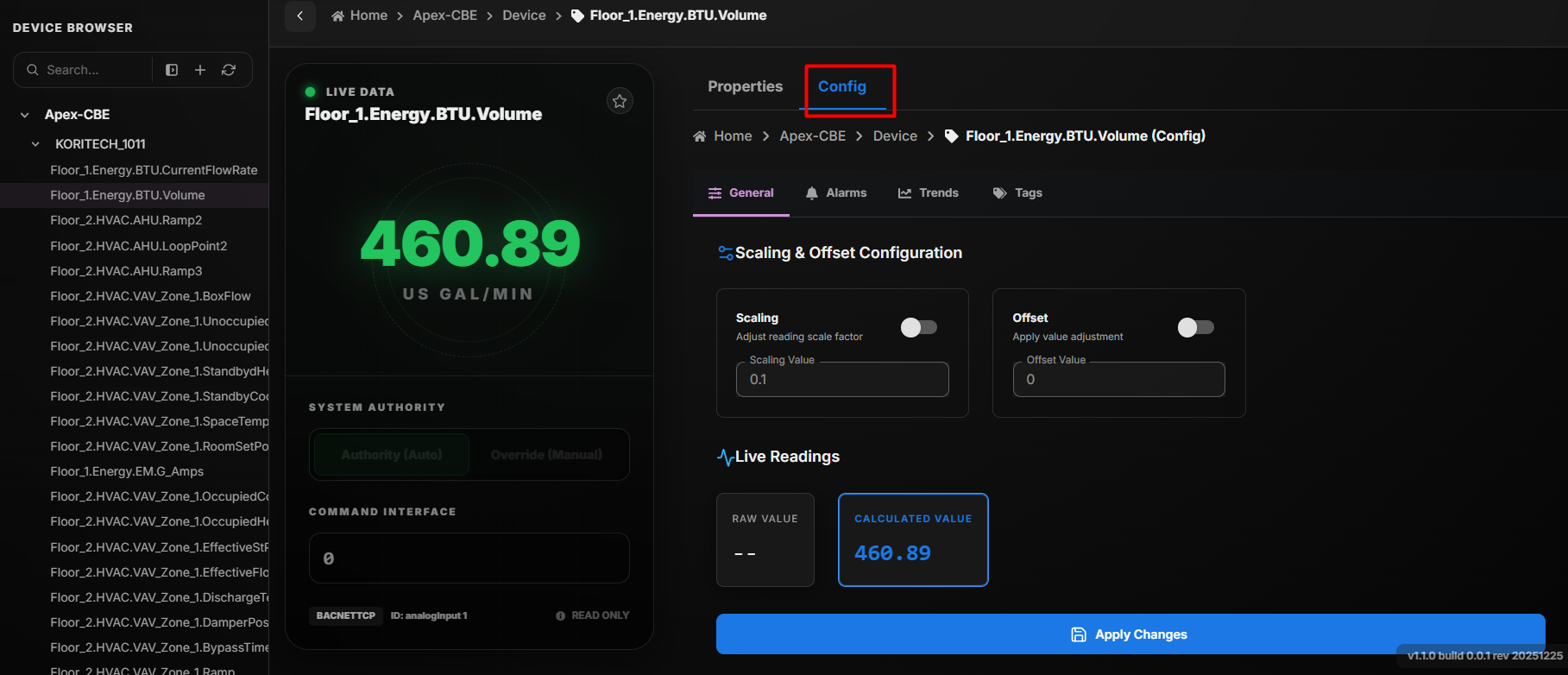 PointConfig
The Point Configuration tab consists of three options for each point:
- General — Configure scaling and offset values for the point. View live reading, raw value, and calculated value, and apply changes as needed.
- Alarm — Configure alarm conditions and thresholds for the point.
- Trends — Enable and manage trend logging to track point values over time.
- Tags — Assign tags to the point for easier identification, filtering, and grouping.
These options allow you to customize how each point is monitored, logged, and organized within the Bacsys Cloud Platform.
General Settings
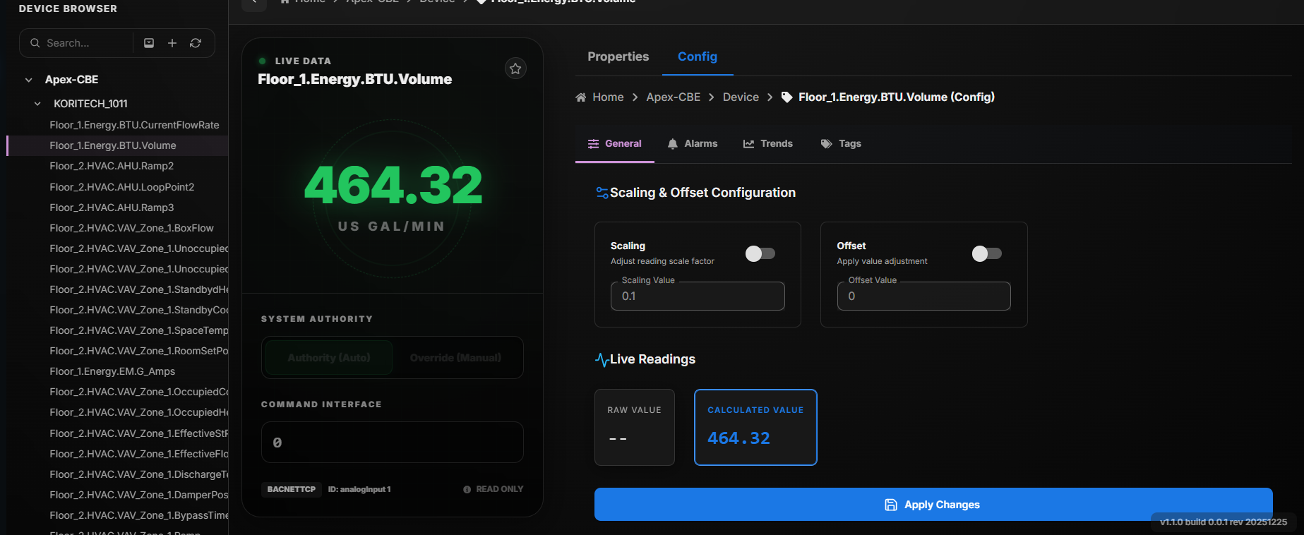 PointConfig
In the General section, users can configure Scaling and Offset values to adjust the point reading.
The system displays:
- Live Reading – The current real-time value.
- Raw Value – The original value received from the device.
- Calculated Value – The final value after applying scaling and offset.
Click Apply Changes to save and apply the updated settings.
Alarm Configuration
The Alarm configuration allows you to define threshold-based alerts for a point. When the point's value crosses the defined high limit, the system generates an alarm, helping you monitor critical conditions in real time.
You can set the alarm priority, customize alert messages, and enable or disable alarm conditions based on your operational needs.
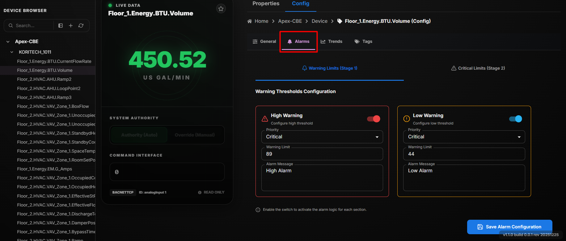 Point Configuration - Alarm
Warning Limits Stage1
| Field | Description |
|---|---|
| Alarm High Warning Limit Enable | When ticked, enables the high limit alarm for the point. When unticked, disables the high limit warning alarm. |
| Alarm Low Warning Limit Enable | When ticked, enables the low limit alarm for the point. When unticked, disables the low limit warning alarm. |
| Alarm High Priority | Allows you to set the priority level for the alarm, such asCritical, High, or Low. |
| Alarm Low Priority | Allows you to set the priority level for the alarm, such asCritical, High, or Low. |
| High Waring Limit Value | If the customer sets a point value and it exceeds the high warning limit, a High Warning Limit Value alarm will be triggered. |
| Low Waring Limit Value | If the customer sets a point value and it exceeds the low warning limit, a Low Warning Limit Value alarm will be triggered. |
| High Waring Limit Message | Enter a custom message that will be displayed when the high warning limit alarm is triggered. |
| Low Waring Limit Message | Enter a custom message that will be displayed when the low warning limit alarm is triggered. |
| Save | Click the Save button to apply and save the configure the changes. |
Critical Limits Stage 2
| Field | Description |
|---|---|
| Alarm High Limit Enable (Checkbox) | When ticked, enables the high limit alarm for the point. When unticked, disables the high limit alarm. |
| Alarm Low Limit Enable(Checkbox) | When ticked, enables the low limit alarm for the point. When unticked, disables the low limit alarm. |
| Alarm High Priority | Allows you to set the priority level for the alarm, such asCritical, High, or Low. |
| Alarm Low Priority | Allows you to set the priority level for the alarm, such asCritical, High, or Low. |
| High Limit Value | If the customer sets a point value and it exceeds the high limit, a High Limit Value alarm will be triggered. |
| Low Limit Value | If the customer sets a point value and it exceeds the low limit, a Low Warning Limit Value alarm will be triggered. |
| High Limit Message | If the customer sets a message and it exceeds the high limit, a High Limit Message alarm will be triggered. |
| Low Limit Message | If the customer sets a message and it exceeds the low limit, a low Limit Message alarm will be triggered. |
| Save | Click and save the button to apply and save the configure the changes |
Trends Configuration:
The Trend feature allows you to record and track the value changes of a point over time. This helps in monitoring patterns, identifying anomalies, and optimizing system performance based on historical data.
You can configure trends by defining the recording interval, specifying active days, and setting a time range to control when the point’s data should be logged. Additionally, the platform allows you to import trend values from a CSV file, enabling historical data uploads or external data integration.
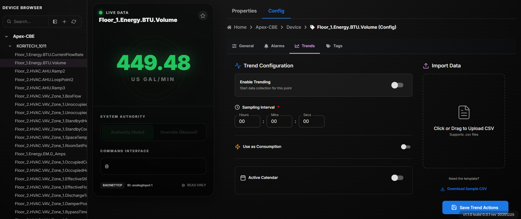 Point configuration - Trends
Trend Configuration
| Field | Description |
|---|---|
| Enable Trend | When selected, trend recording is enabled for the point. When unselected, trend recording is disabled. |
| Sampling Interval | Defines the time interval at which trend data will be recorded. |
| Enable Trend Active Calendar | When selected, enables the trend scheduling functionality. When unselected, scheduling is disabled. |
| Consumption | Enables tracking and recording of consumption-based data for the selected point. |
| Import CSV | Allows importing a CSV file to use its values as trend data for the point. |
| Save | Click the Save button to apply and store the configured changes. |
Tags Configuration:
Tags are user-defined labels that help categorize and organize points within the Bacsys Cloud Platform. Assigning tags to points makes it easier to search, filter, and group related data for efficient monitoring and management.
You can either select from existing tags or create new ones, allowing you to maintain a structured and meaningful naming convention across your devices and points.
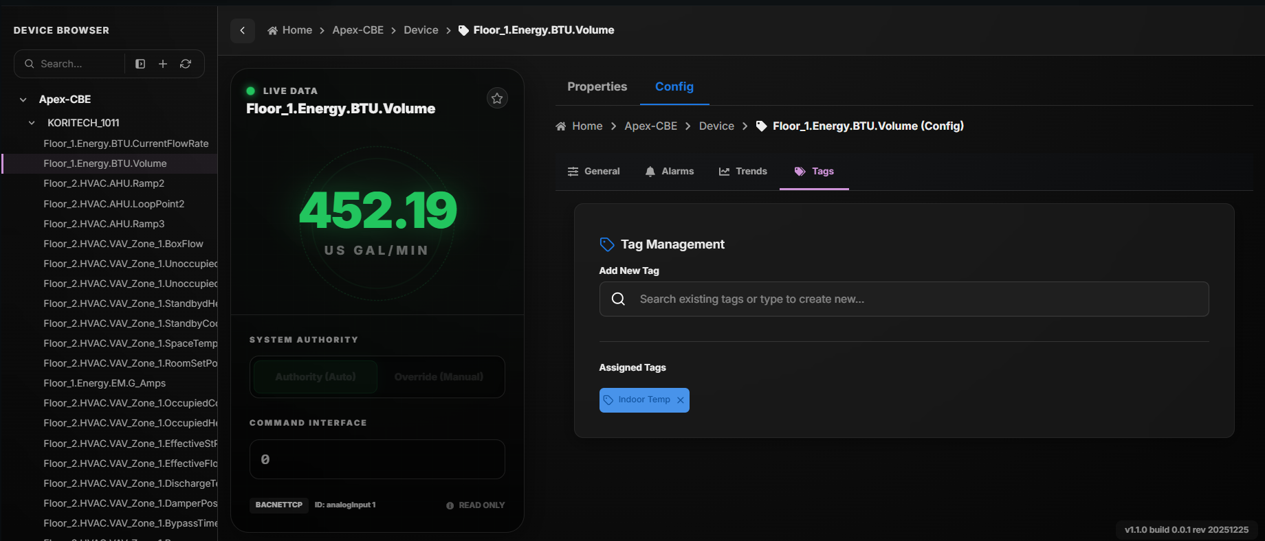 Point configuration - Tags
| Field | Description |
|---|---|
| Search & Add Tags | Search for an existing tag or create a new tag with the given name, and assign it to the point. |
| Added Tags | Displays the list of tags currently assigned to the point. |
Expand All
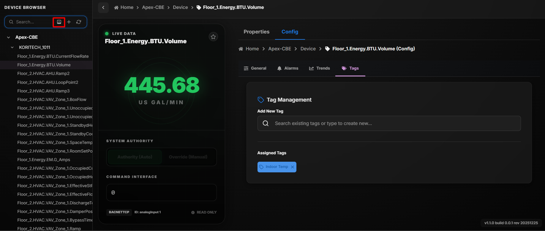 Expand All
The Expand All option allows users to expand the complete device hierarchy.
When the Expand All button is clicked:
- All networks are expanded.
- All devices under each network are displayed.
- All points under each device are shown.
This feature provides a full hierarchical view from network to device to point without manually expanding each section.
Refresh
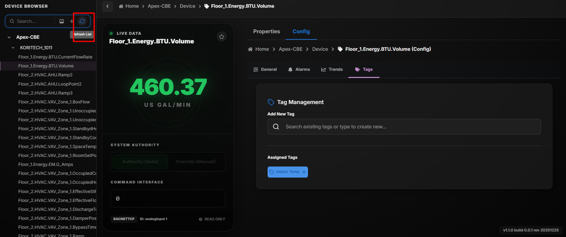 Refresh
The Refresh option allows users to update the current view.
When the Refresh button is clicked:
- The system reloads the latest data from the controller.
- Updated network, device, and point information is displayed.
- Any recent changes are reflected in the interface.
This ensures that users are viewing the most up-to-date information.