

Configuring BACnet TCP/IP
The BACnet TCP/IP protocol allows APEX to communicate with BACnet-enabled devices over an Ethernet network. Using BACnet TCP/IP, you can create a network, discover devices, add points, and monitor real-time data for building automation and control systems.
Creating a BACnet TCP/IP Network
-
Open the Devices module from the sidebar.
-
Click Create Network.
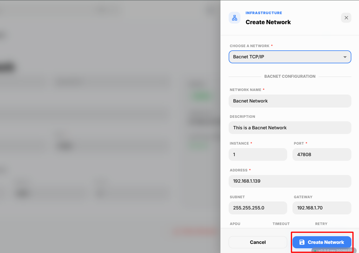
A Create Network popup appears.
-
From the Choose a Network dropdown, select BACnet TCP/IP.
Enter the following network details:
Field Description Network Name Enter a unique name for the BACnet TCP/IP network. Network Description Enter a brief description to help identify the network. Instance Enter the BACnet device instance number. Each device on the BACnet network must have a unique instance number. Port Enter the communication port used by the BACnet TCP/IP network. The default BACnet UDP port is 47808 (0xBAC0) unless otherwise configured. Address Enter the IP address of the BACnet TCP/IP network interface. Subnet Enter the subnet mask of the network. Gateway Enter the gateway IP address for the network. APDU Enter the maximum APDU (Application Protocol Data Unit) size supported by the device. Timeout Specify the communication timeout value used while communicating with BACnet devices. Retry Enter the number of retry attempts if communication fails. -
After entering all the required details, click Create Network.
-
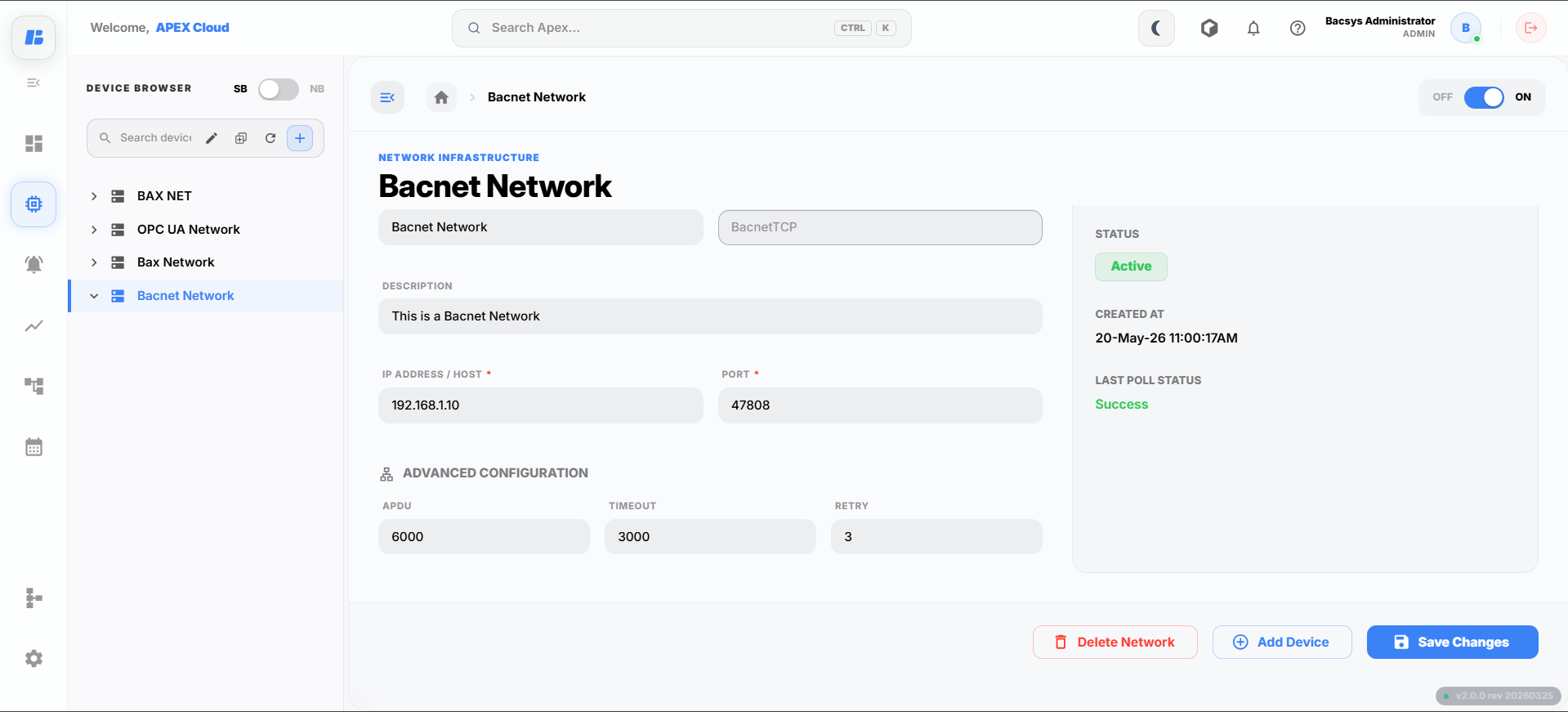
Once the network is created successfully, it is displayed in the network list.
Discovering and Adding Devices
After creating the BACnet TCP/IP network, discover the BACnet devices connected to the network.
-
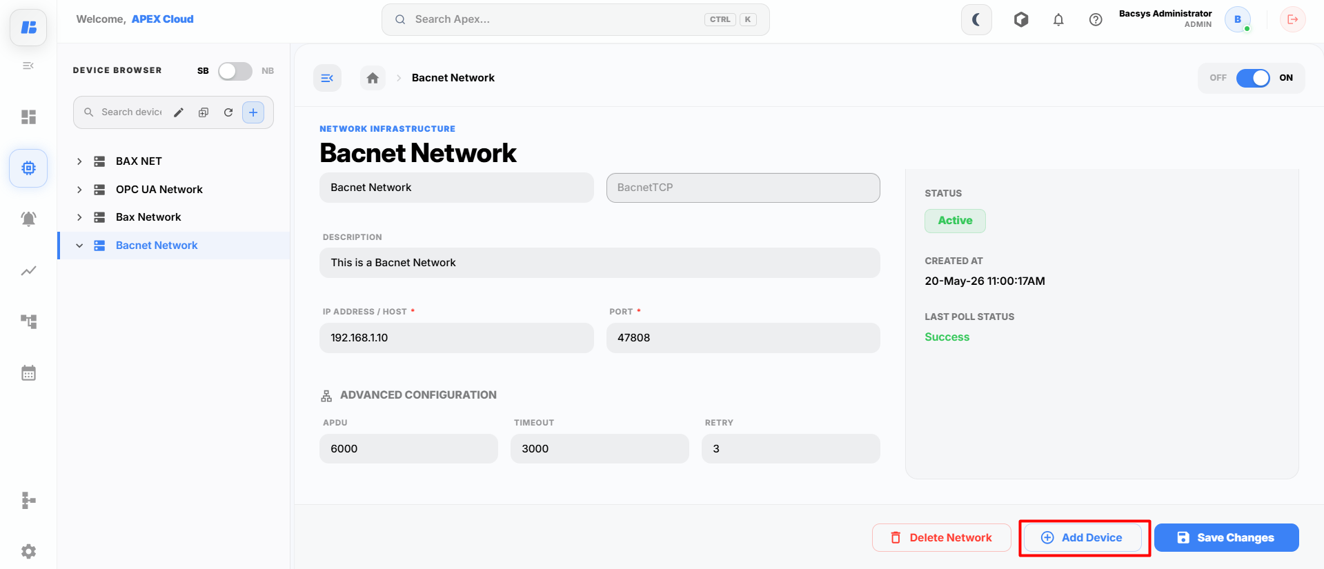
Open the BACnet TCP/IP network.
-
Click Add Device.
-
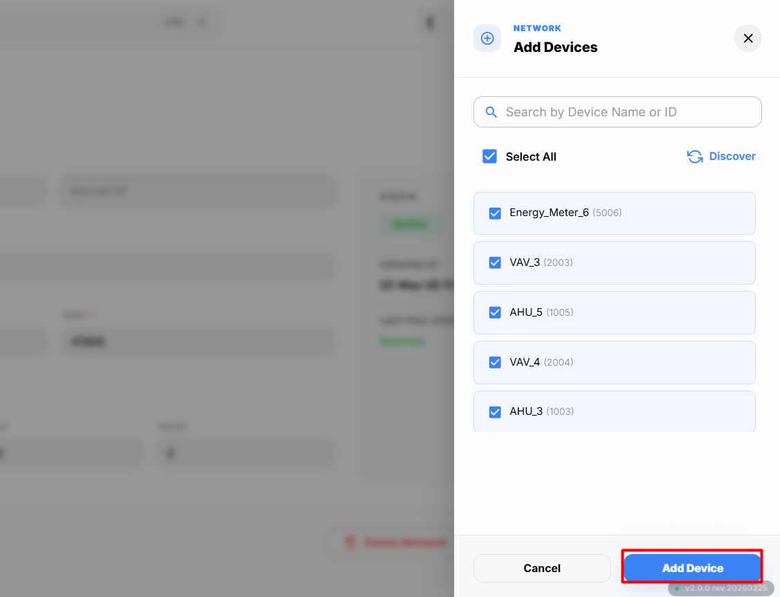
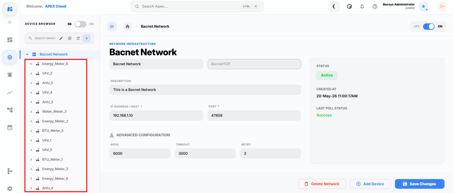
The Device Discovery window displays all the available BACnet devices.
Select the required device(s) and click Add.
-
The selected devices are added to the network and displayed in the device list.
Discovering and Adding Points
After adding a BACnet device, you can add the required points for monitoring.
-
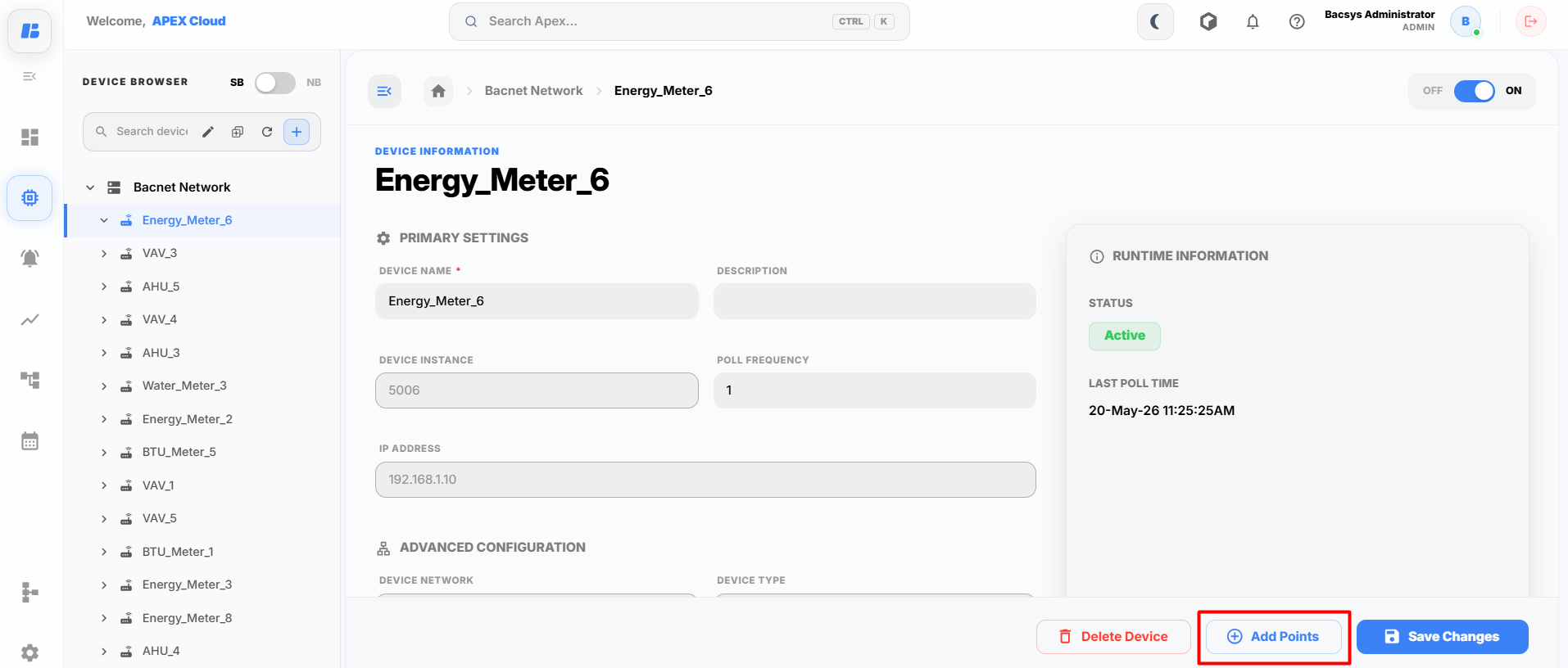
Open the required BACnet device.
-
Click Add Points.
-
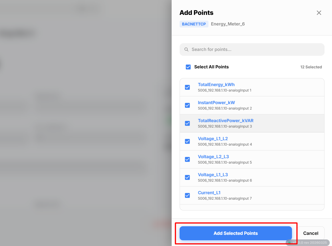
The Points Discovery window displays all the available BACnet points.
Select the required points or click Select All Points to add every available point.
Click Add Selected Points.
-
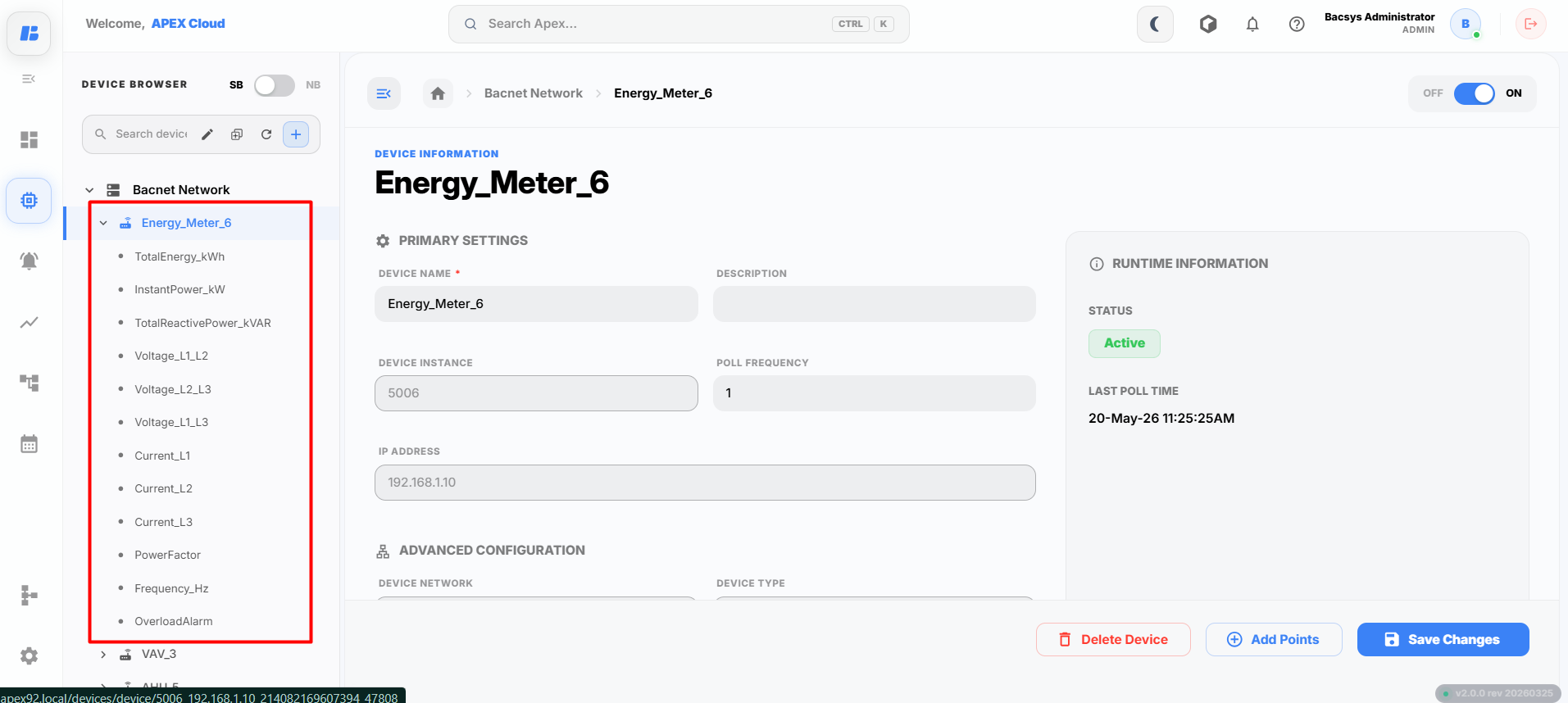
The selected points are added to the device and displayed in the points list.
Viewing Point Details
After adding the required points, you can view their properties and live values.
-
Click any point from the points list.
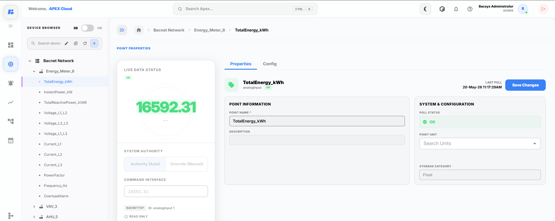
The point details page displays the following information:
- Live Value – Displays the current value of the selected point.
- Point Properties – Displays the point name, object type, object instance, and other configured properties.
- Communication Status – Indicates whether the point is communicating successfully.
- Timestamp – Displays the date and time of the latest value update.
- Real-Time Monitoring – Continuously updates the point value while communication is active.
Point Configuration
After selecting a point, click the Config tab to configure the point settings. The Config tab contains four sections:
- General
- Alarms
- Trends
- Tags
General Configuration
The General tab allows you to configure linear mapping, scaling, and offset values for the selected point.
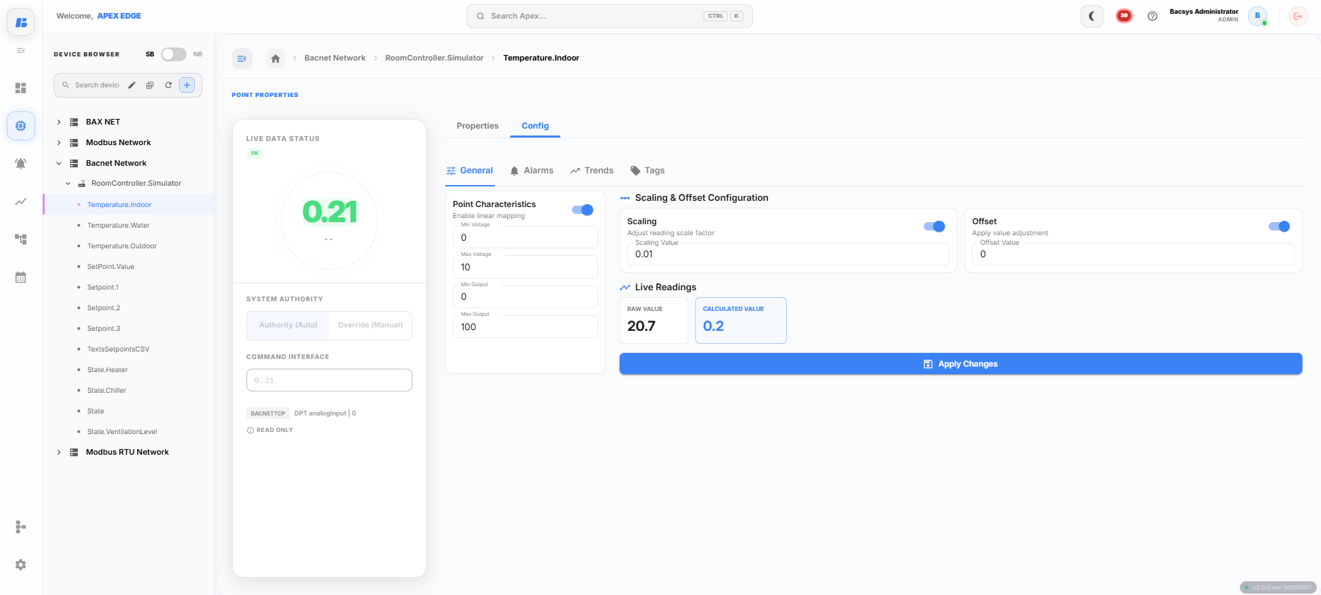
| Section | Field | Description |
|---|---|---|
| Point Characteristics | Enable Linear Mapping | Enables linear mapping for the selected point. |
| Min Voltage | Specifies the minimum input voltage. | |
| Max Voltage | Specifies the maximum input voltage. | |
| Min Output | Specifies the minimum output value after mapping. | |
| Max Output | Specifies the maximum output value after mapping. | |
| Scaling & Offset Configuration | Scaling | Enables scaling for the point value. |
| Scaling Value | Multiplies the incoming value by the specified scaling factor. | |
| Offset | Enables offset adjustment. | |
| Offset Value | Adds or subtracts the specified offset from the calculated value. | |
| Live Readings | Raw Value | Displays the value received directly from the device. |
| Calculated Value | Displays the final value after applying scaling and offset. |
After configuring the required settings, click Apply Changes to save the configuration.
Alarm Configuration
The Alarms tab allows you to configure warning and critical alarm thresholds for the selected point.
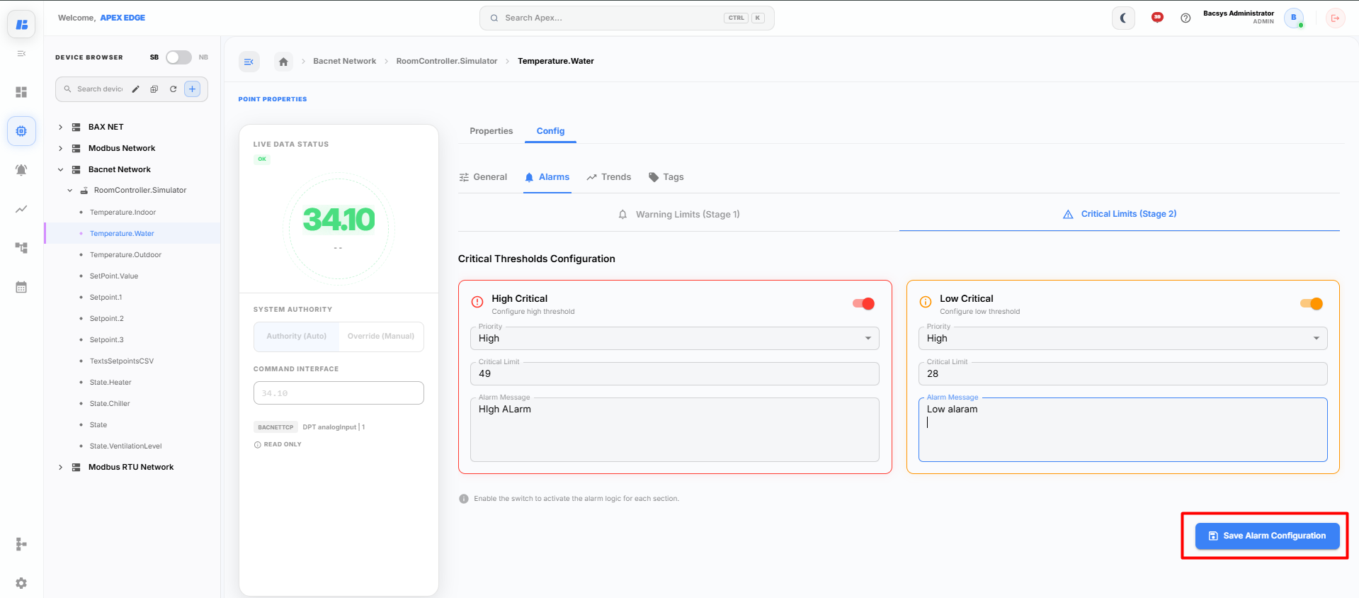
The alarm configuration is divided into two stages:
- Stage 1 – Warning Limits
- Stage 2 – Critical Limits
Stage 1 – Warning Limits
| Field | Description |
|---|---|
| High Warning | Enables or disables the high warning alarm. |
| Priority | Select the alarm priority. |
| Warning Limit | Enter the upper warning threshold value. |
| Alarm Message | Enter the message displayed when the warning alarm is triggered. |
| Low Warning | Enables or disables the low warning alarm. |
| Priority | Select the alarm priority. |
| Warning Limit | Enter the lower warning threshold value. |
| Alarm Message | Enter the message displayed when the low warning alarm is triggered. |
Stage 2 – Critical Limits
| Field | Description |
|---|---|
| High Critical | Enables or disables the high critical alarm. |
| Priority | Select the alarm priority. |
| Critical Limit | Enter the upper critical threshold value. |
| Alarm Message | Enter the message displayed when the critical alarm is triggered. |
| Low Critical | Enables or disables the low critical alarm. |
| Priority | Select the alarm priority. |
| Critical Limit | Enter the lower critical threshold value. |
| Alarm Message | Enter the message displayed when the low critical alarm is triggered. |
After configuring the required alarm settings, click Save Alarm Configuration.
Trend Configuration
The Trends tab allows you to configure data logging and trend collection for the selected point.
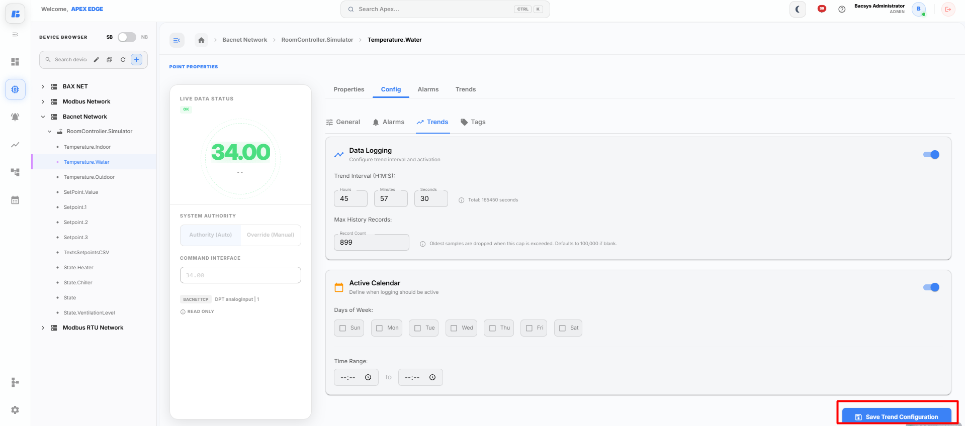
Data Logging
| Field | Description |
|---|---|
| Enable Data Logging | Enables or disables trend logging. |
| Trend Interval (Hours) | Specifies the number of hours between data samples. |
| Trend Interval (Minutes) | Specifies the number of minutes between data samples. |
| Trend Interval (Seconds) | Specifies the number of seconds between data samples. |
| Max History Records | Specifies the maximum number of trend records to retain. Older records are automatically removed when this limit is reached. |
Active Calendar
| Field | Description |
|---|---|
| Enable Active Calendar | Enables scheduled trend logging. |
| Days of Week | Select the days on which trend logging should be active. |
| Start Time | Specifies when trend logging begins. |
| End Time | Specifies when trend logging stops. |
After completing the configuration, click Save Trend Configuration.
Tags Configuration
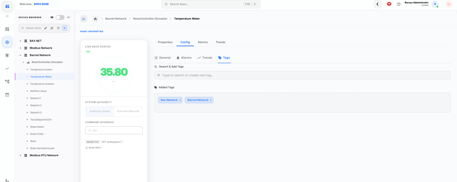
The Tags tab allows you to assign one or more tags to the selected point for easier organization and searching.
| Field | Description |
|---|---|
| Search & Add Tags | Search for an existing tag or create a new tag by entering a name. |
| Added Tags | Displays all tags currently assigned to the selected point. |
| Remove Tag | Click the × icon on a tag to remove it from the point. |
To assign a tag:
- Enter the tag name in the Search & Add Tags field.
- Select an existing tag or create a new one.
- The selected tag is automatically added to the Added Tags section.
- Multiple tags can be assigned to a single point.