

Configuring SNMP
Creating an SNMP Network
The SNMP network allows the platform to communicate with SNMP-enabled devices and retrieve monitoring data using the Simple Network Management Protocol (SNMP).
-
Navigate to the Devices module from the sidebar.
-
Click the + (Add) icon.
-
Drop to SNMP into the Create Network window.
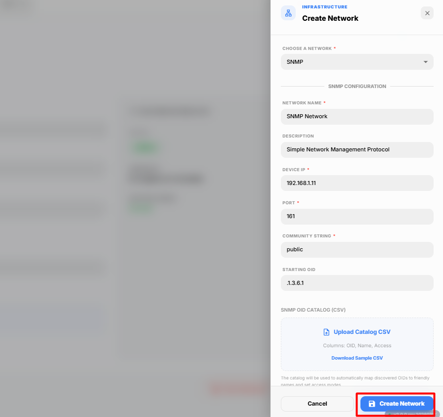
The Create Network dialog box appears.
-
Enter the required network details.
Field Description Network Name Enter a unique name to identify the SNMP network. Description Enter a brief description of the SNMP network. Device IP Enter the IP address of the SNMP-enabled device. Port Enter the SNMP communication port. The default port is 161. Community String Enter the community string used to authenticate SNMP requests (for example, public).Starting OID Enter the starting Object Identifier (OID) from which the platform begins discovering SNMP objects. SNMP OID Catalog (CSV) Upload a CSV file containing OID definitions to map discovered OIDs to meaningful names and access modes. SNMP Version Select the SNMP version supported by the device (for example, v1, v2c).
SNMP OID Catalog
The SNMP OID Catalog (CSV) option allows you to upload a catalog file that maps OIDs to user-friendly names.
- Click Upload Catalog CSV to upload an SNMP OID catalog.
- Click Download Sample CSV to download a sample catalog file.
- The uploaded catalog is used during point discovery to automatically identify OIDs and their access modes.
-
After entering all the required information, click Create Network.
The SNMP network is successfully created and is displayed in the Devices module.
Adding an SNMP Device
After creating the SNMP network, add the discovered device to the network for monitoring.
-
Select the newly created SNMP network from the Devices module.
-
Click Add Device.
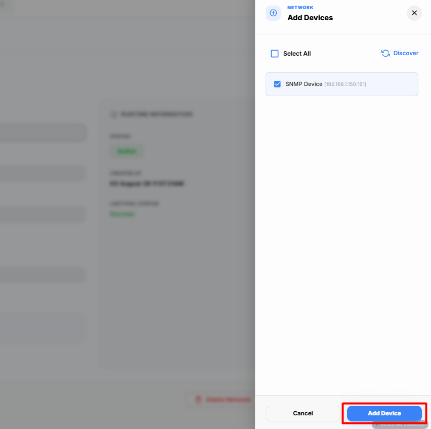
The Add Device dialog box appears, displaying the list of discovered SNMP devices.
-
Select the required device from the available list.
Review the device information and ensure that you have selected the correct device.
-
Click Add Device.
The selected SNMP device is added successfully to the network and is displayed under the selected SNMP Network.
Adding Points
After adding the SNMP device, you can create monitoring points from the discovered OIDs.
-
Select the newly added SNMP Device.
-
Click Add Points.
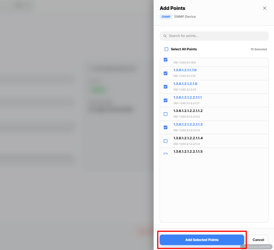
The Add Points dialog box appears, displaying the discovered SNMP points.
-
Review the available points.
You can update the point details before adding them to the device.
The following fields can be modified:
Field Description Point Name Enter or modify the name of the point. Point Description Enter or update a description for the point. Point Unit Specify the unit of measurement for the point, if required. -
Select the points that you want to add.
-
Click Add Points.
The selected points are successfully added to the SNMP device and are displayed under the selected device in the Devices module.
Point Properties
After adding the SNMP points, select a point from the Device Browser to view and configure its properties.
The point page consists of two tabs:
- Properties
- Config
Properties
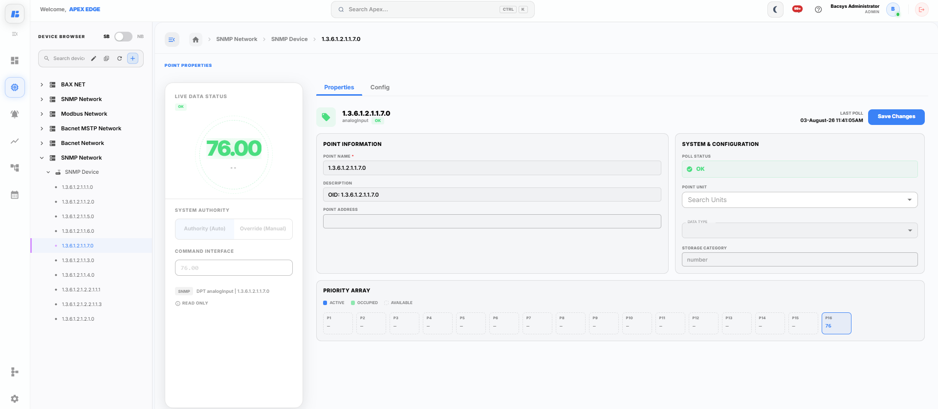
The Properties tab allows you to view and modify the basic information of the selected point.
Live Data Status
The Live Data Status section displays the current value of the selected point along with its communication status.
It also provides:
- Current live value
- Point communication status
- Command interface
- System authority information
Point Information
The Point Information section displays the basic details of the selected point.
| Field | Description |
|---|---|
| Point Name | Displays the name of the point. You can modify the point name if required. |
| Description | Enter or update a description for the point. |
| Point Address | Displays or allows you to configure the point address or OID. |
System & Configuration
The System & Configuration section displays the configuration details of the selected point.
| Field | Description |
|---|---|
| Poll Status | Displays whether the point is communicating successfully. |
| Point Unit | Select the engineering unit for the point value. |
| Data Type | Displays or selects the data type of the point. |
| Storage Category | Displays the storage type used for the point value. |
Priority Array
The Priority Array displays the current priority levels assigned to the point.
The priority array contains sixteen priority levels (P1–P16) that indicate the active command priority.
The currently active priority is highlighted.
After making the required changes, click Save Changes to update the point configuration.
Config
Select the Config tab to configure the operational settings of the selected point.
The Config tab contains the following sections:
- General
- Alarms
- Trends
- Tags
General
The General section allows you to configure how the point value is processed before it is displayed.
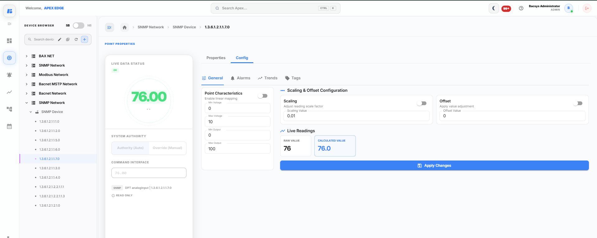
Point Characteristics
Enable Linear Mapping to convert the raw input value into the required engineering range.
Configure the following parameters:
| Field | Description |
|---|---|
| Min Voltage | Specifies the minimum input value. |
| Max Voltage | Specifies the maximum input value. |
| Min Output | Specifies the minimum mapped output value. |
| Max Output | Specifies the maximum mapped output value. |
Linear Mapping is useful when converting sensor values into engineering units.
Scaling
Enable Scaling to multiply the incoming value by a scaling factor.
| Field | Description |
|---|---|
| Scaling Value | Specifies the multiplier applied to the point value. |
Example:
If the raw value is 76 and the scaling value is 0.01, the calculated value becomes 0.76.
Offset
Enable Offset to increase or decrease the calculated value by a fixed amount.
| Field | Description |
|---|---|
| Offset Value | Specifies the value added to or subtracted from the calculated value. |
Example:
If the calculated value is 76 and the offset is 5, the displayed value becomes 81.
Live Readings
The Live Readings section displays both the original value received from the device and the processed value after applying scaling and offset.
| Reading | Description |
|---|---|
| Raw Value | Displays the original value received from the SNMP device. |
| Calculated Value | Displays the processed value after applying scaling and offset. |
After configuring the required settings, click Apply Changes to save the configuration.
Alarms
The Alarms section allows you to configure alarm thresholds for the selected point.
Two alarm levels are available:
- High Critical
- Low Critical
For each alarm, configure the following:
| Field | Description |
|---|---|
| Enable | Enables or disables the alarm configuration. |
| Priority | Specifies the alarm priority. |
| Critical Limit | Defines the threshold value that triggers the alarm. |
| Alarm Message | Enter the message displayed when the alarm is triggered. |
After configuring the required alarm settings, click Save Alarm Configuration.
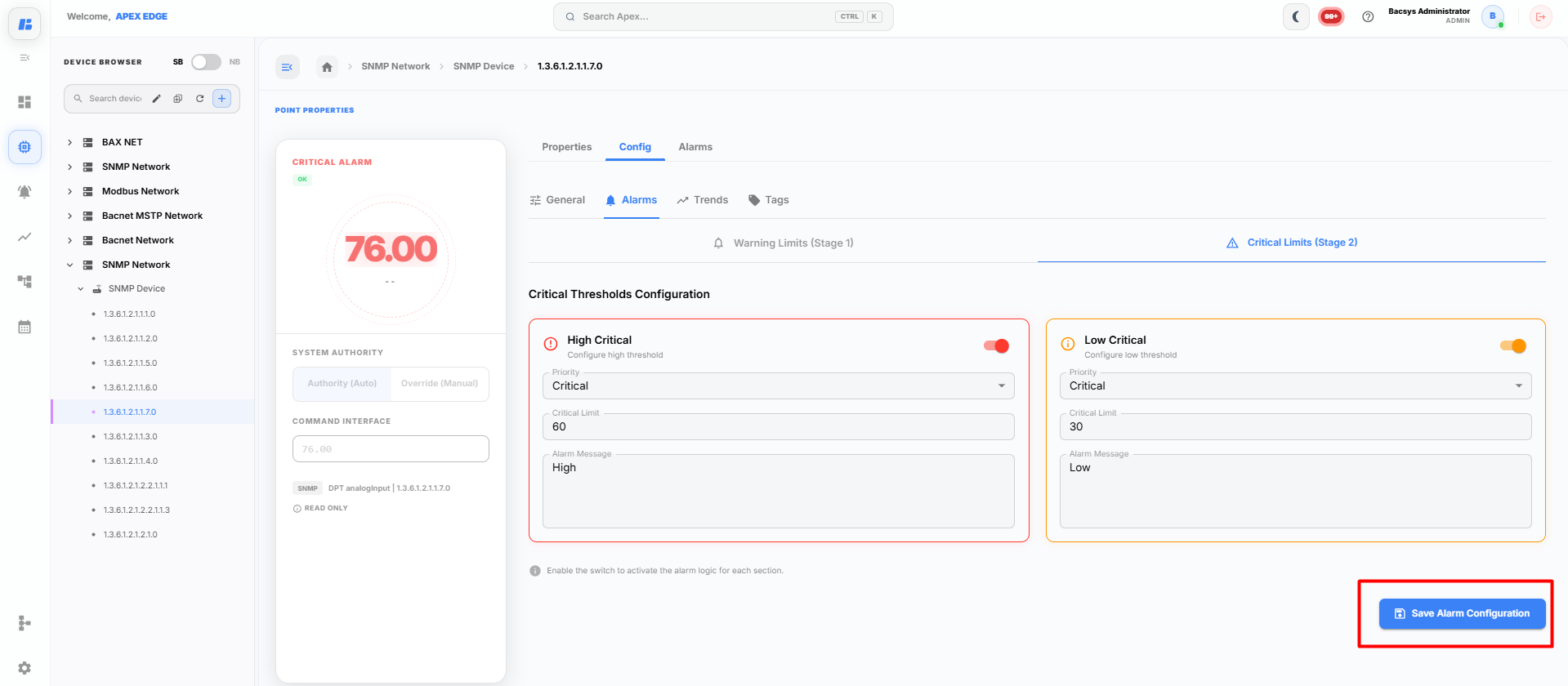
The platform continuously compares the live point value with the configured alarm thresholds. When the point value reaches or exceeds the configured limit, the corresponding alarm is generated.
Trends
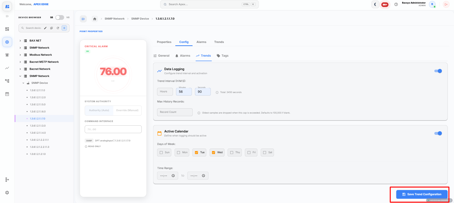
The Trends section allows you to configure historical data logging for the selected point.
Data Logging
Enable Data Logging and configure the following settings:
| Field | Description |
|---|---|
| Trend Interval | Specifies how often the point value is recorded. |
| Max History Records | Specifies the maximum number of trend records to retain. |
Active Calendar
The Active Calendar defines when trend logging should be active.
Configure:
- Days of the week
- Start Time
- End Time
After completing the configuration, click Save Trend Configuration.
Tags
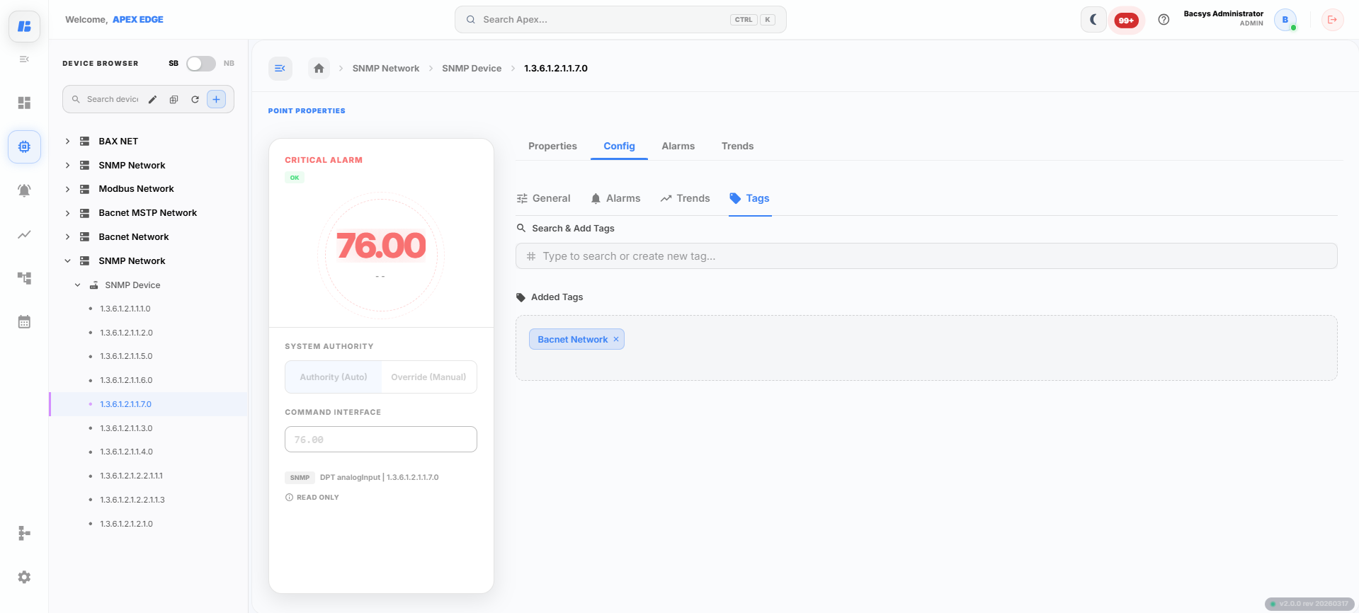
The Tags section allows you to organize and categorize points.
To add a tag:
- Enter the tag name in the Search & Add Tags field.
- Select an existing tag or create a new tag.
- The selected tag is displayed under Added Tags.
Tags help organize points and make searching and filtering easier throughout the platform.
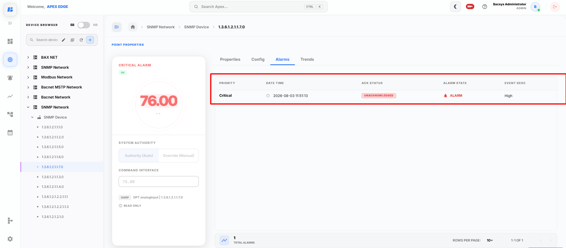
Alarm Status
After configuring the required alarm thresholds, click Save Alarm Configuration.
The platform continuously monitors the point value against the configured alarm limits. When the point value reaches or exceeds the configured threshold, the corresponding alarm is generated.
To view the generated alarm:
- Navigate to the Alarms module from the sidebar.
- Select the required alarm from the alarm list.
- Open the associated point to view the alarm details and its current status.
This allows you to verify whether the alarm has been triggered for the selected point based on the configured alarm thresholds.
Viewing Trends
To view the historical data of a point, select the required point and click the Trends tab.
The Trends page displays the historical data in both Table and Chart views.
Table View
The Table view displays the recorded values of the selected point in a tabular format.
The following options are available:
| Option | Description |
|---|---|
| Start Date | Select the start date for retrieving trend data. |
| End Date | Select the end date for retrieving trend data. |
| Export | Exports the displayed trend data to a CSV file. |
| Refresh | Refreshes the trend data for the selected date range. |
| Clear | Clears the selected date range and displayed data. |
| Delta | Enables or disables delta value display. |
| Edit | Enables or disables edit mode using the toggle button. |
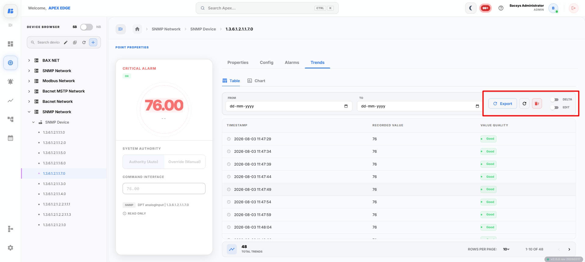
Chart View
The Chart view displays the historical data of the selected point in graphical format.
The following options are available:
| Option | Description |
|---|---|
| Start Date | Select the start date for displaying trend data. |
| End Date | Select the end date for displaying trend data. |
| Export | Exports the displayed chart data. |
| Refresh | Refreshes the chart based on the selected date range. |
| Clear | Clears the selected filters and chart data. |
| Delta | Enables or disables delta value display on the chart. |
| Edit | Enables or disables edit mode using the toggle button. |
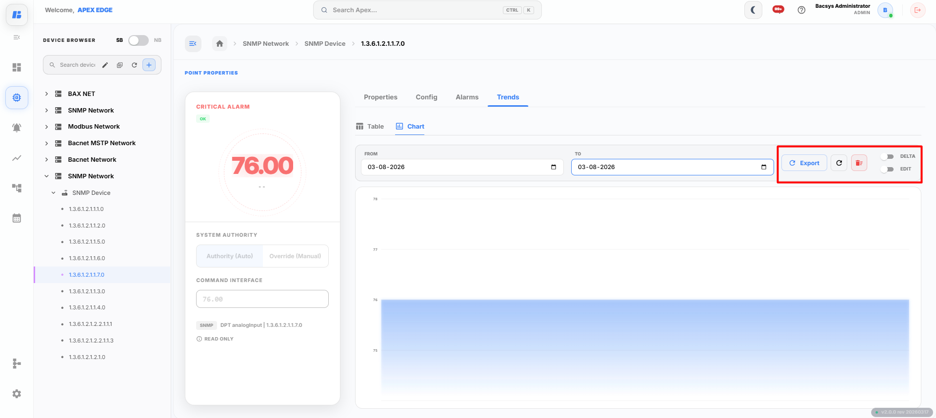
The Table and Chart views provide different ways to analyze historical point data. You can filter the data using a date range, refresh the displayed information, export the results, and use the Delta and Edit options as required for further analysis.
Complete Workflow
Follow the steps below to configure an SNMP network, add devices and points, configure point settings, and monitor live and historical data.
- Open the Devices module.
- Click the + (Add) icon.
- Drag and drop SNMP into the Create Network window.
- Enter the required network details:
- Network Name
- Description
- Device IP
- Port
- Community String
- Starting OID
- SNMP OID Catalog (Optional)
- SNMP Version
- Click Create Network.
- Select the newly created SNMP Network.
- Click Add Device.
- Select the required SNMP device from the discovered device list.
- Click Add Device to add the selected device to the network.
- Select the newly added SNMP Device.
- Click Add Points.
- Review and update the point details, such as:
- Point Name
- Point Description
- Point Unit
- Select the required points and click Add Points.
- Select a point from the Device Browser to view its properties.
- Update the point information if required and click Save Changes.
- Open the Config tab to configure the point settings:
- Configure General settings (Linear Mapping, Scaling, Offset, and Live Readings).
- Configure Alarms and click Save Alarm Configuration.
- Configure Trends and click Save Trend Configuration.
- Add or manage Tags for the point.
- To verify the configured alarms, navigate to the Alarms module and open the required alarm to view the associated point and its current alarm status.
- Open the Trends tab to view the historical data of the selected point in:
- Table View
- Chart View
- Use the available trend options to:
- Select the Start Date and End Date.
- Refresh the displayed data.
- Export trend data.
- Clear the selected filters.
- Enable or disable the Delta option.
- Enable or disable Edit mode.
The SNMP network is now fully configured, allowing you to monitor live point values, manage alarms, analyze historical trends, and organize points using tags.